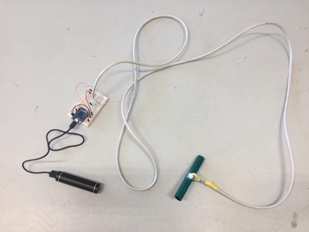
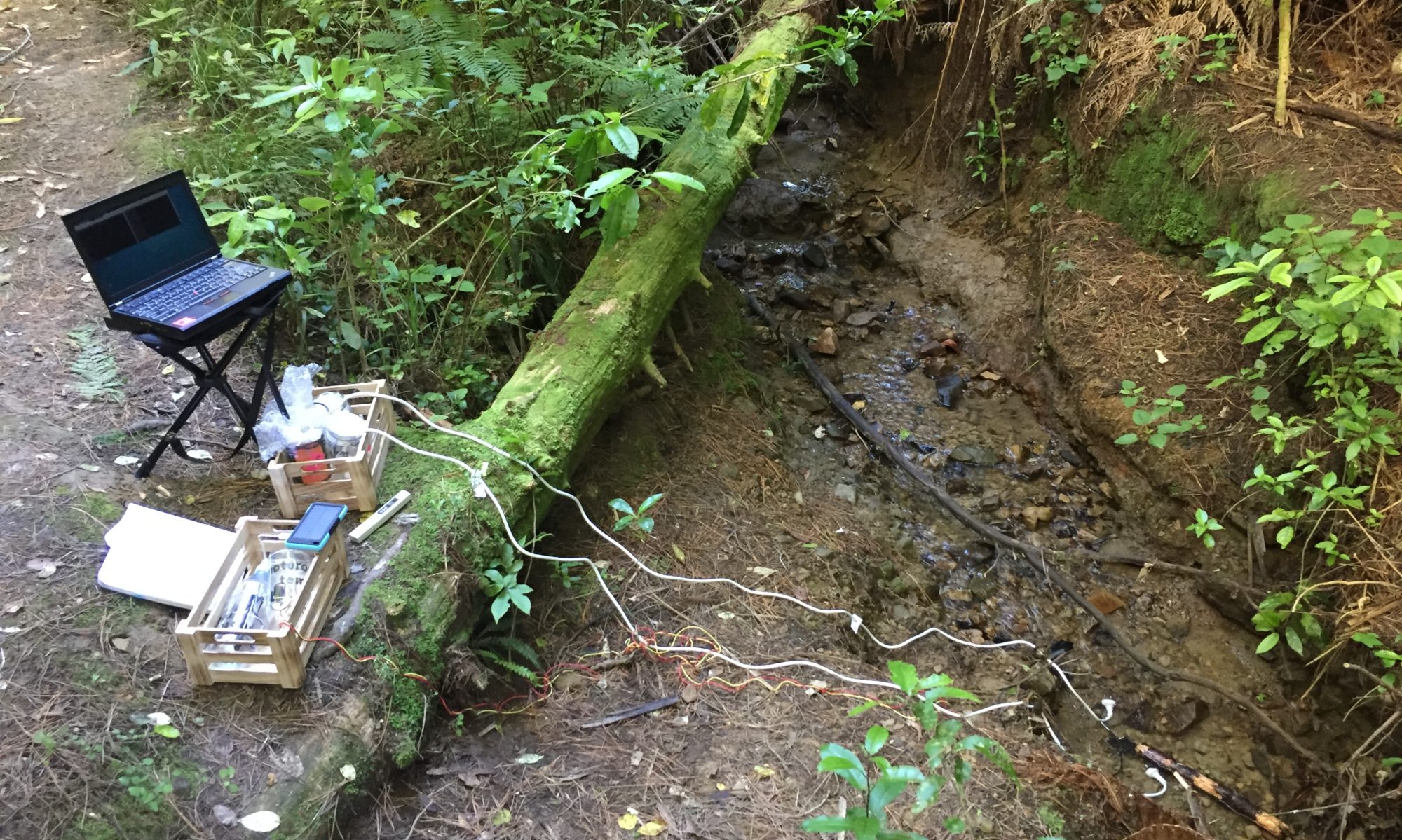
The next iteration of the turbidity sensor requires more thorough waterproofing from the beginning. Prototype I started as a simple proof-of-concept of the component combination ( LED, LDR in a garden hose enclosure) and had no consideration of waterproofing. After that, the focus of Prototype II lay on improving the initial design’s lack of water-proofing and adding long cables so it can be eventually tested out in the field.
Part I: Components, cables and heat shrinking tube
For this turbidity sensor design, I used an approximately two-meter-long stranded core CAT-5 cable to connect my white LED and my LDR to my Wemos D1 board.
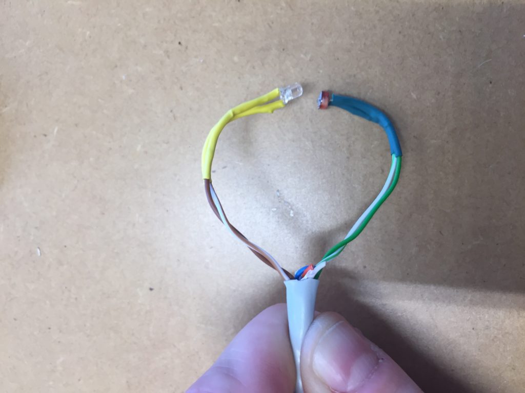
After assembly, I immediately sealed the components that eventually get submerged into the water with heat shrink tubing (yellow for the LED, green for the LDR).
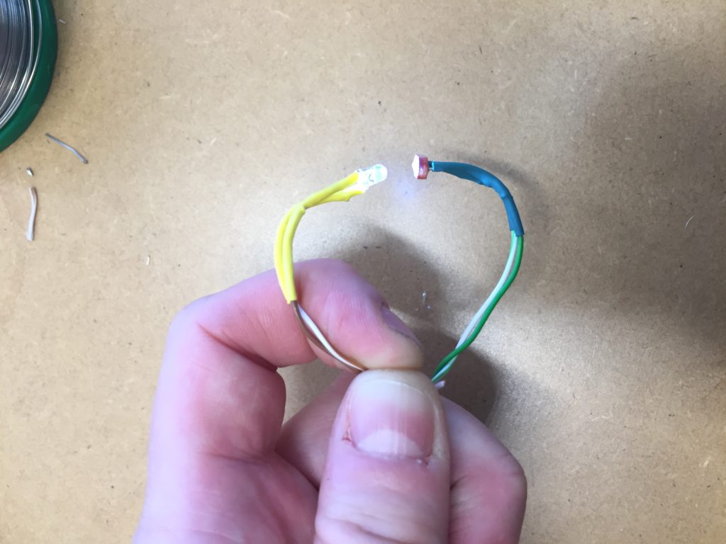
My first attempt at running the test code with the components through the two-meter-long wire went well. I tested the incoming values roughly by concealing the LDR with my finger.
Part II: Housing the components in the “test tube.”
Similar to the previous prototype, I cut a new 10cm piece off the garden hose and drilled two opposing holes of the size of the components in the centre. To attach the LDR and the LDR I used hot glue only this time. The reasoning behind this is that hot glue has a much shorter drying/hardening time than the All Clear sealant. This allows an efficient applying of layer after layer within a relatively short period. The sealant ideally requires overnight drying which means assembly would span several days instead of hours.
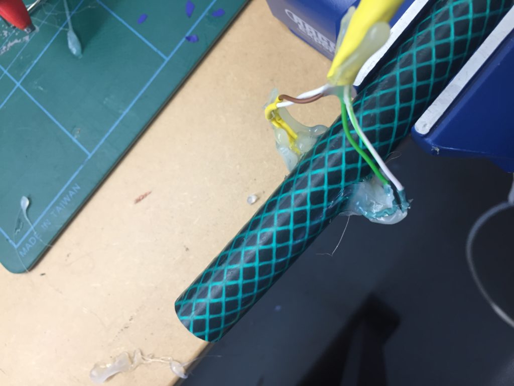
The work with hot glue is messy and requires diligence. Therefor, the purpose of the first layer is to attach the components to the hose and make sure they are facing each other correctly.
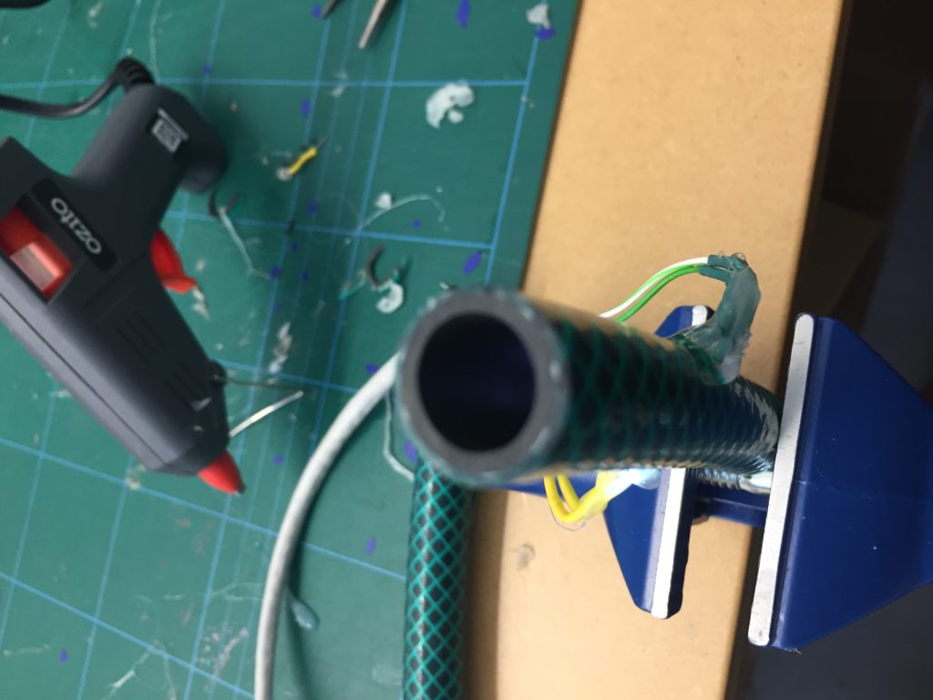
After the first layer has been applied I test that the components have not been damaged in the process of hot glueing. The incoming values look good so far, but I am not entirely happy with the design. It is quite hard to apply hot glue around the components evenly. I already spot some small grooves in the glue that could cause some leaks later on.
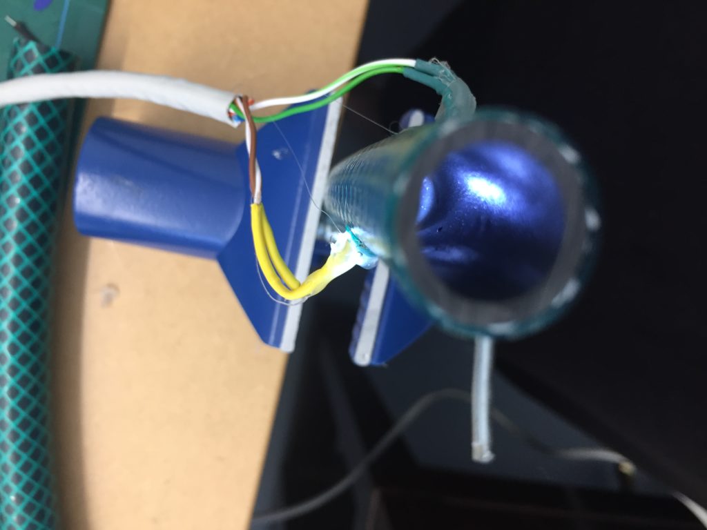
Part III: Dear hot glue, please protect my components
While applying the next layer of hot glue, I have already made peace with the fact that this probe is going to look very odd. Basically, I am looking at a small dark-green piece of garden hose attached to a long cable with semi-transparent blobs of glue. I also notice that the wire close to the components appears to be under strain caused by the angle the components are attached to the hose. I should have immediately bent the connectors at a right angle to avoid this oddly shaped glue blob altogether.
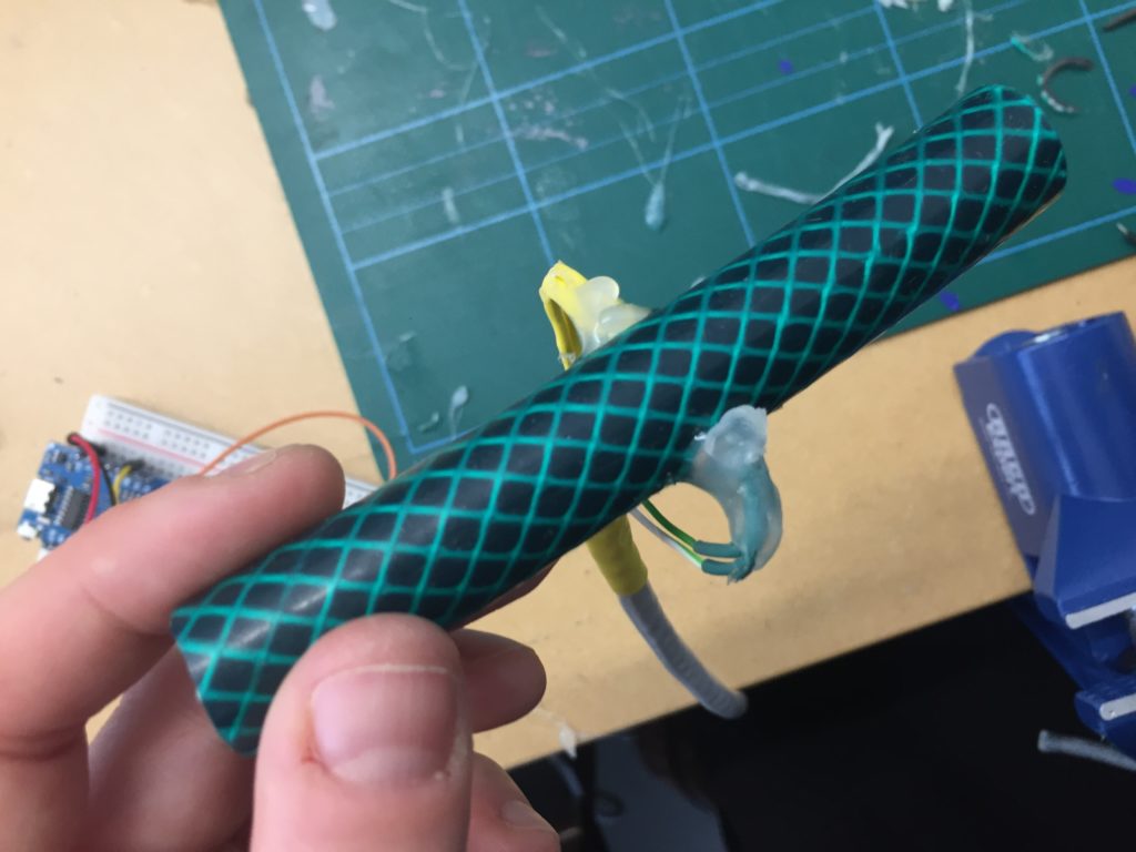
Despite the aesthetic shortcomings of this turbidity sensor design all components seem to be working, and I am ready to compile a version that sends data wirelessly via the MQTT network so I can safely test the design in an underwater setting, without the need of a laptop attached to any submerged components.
