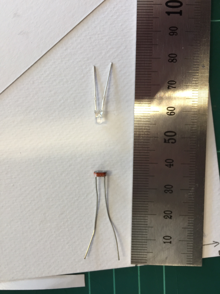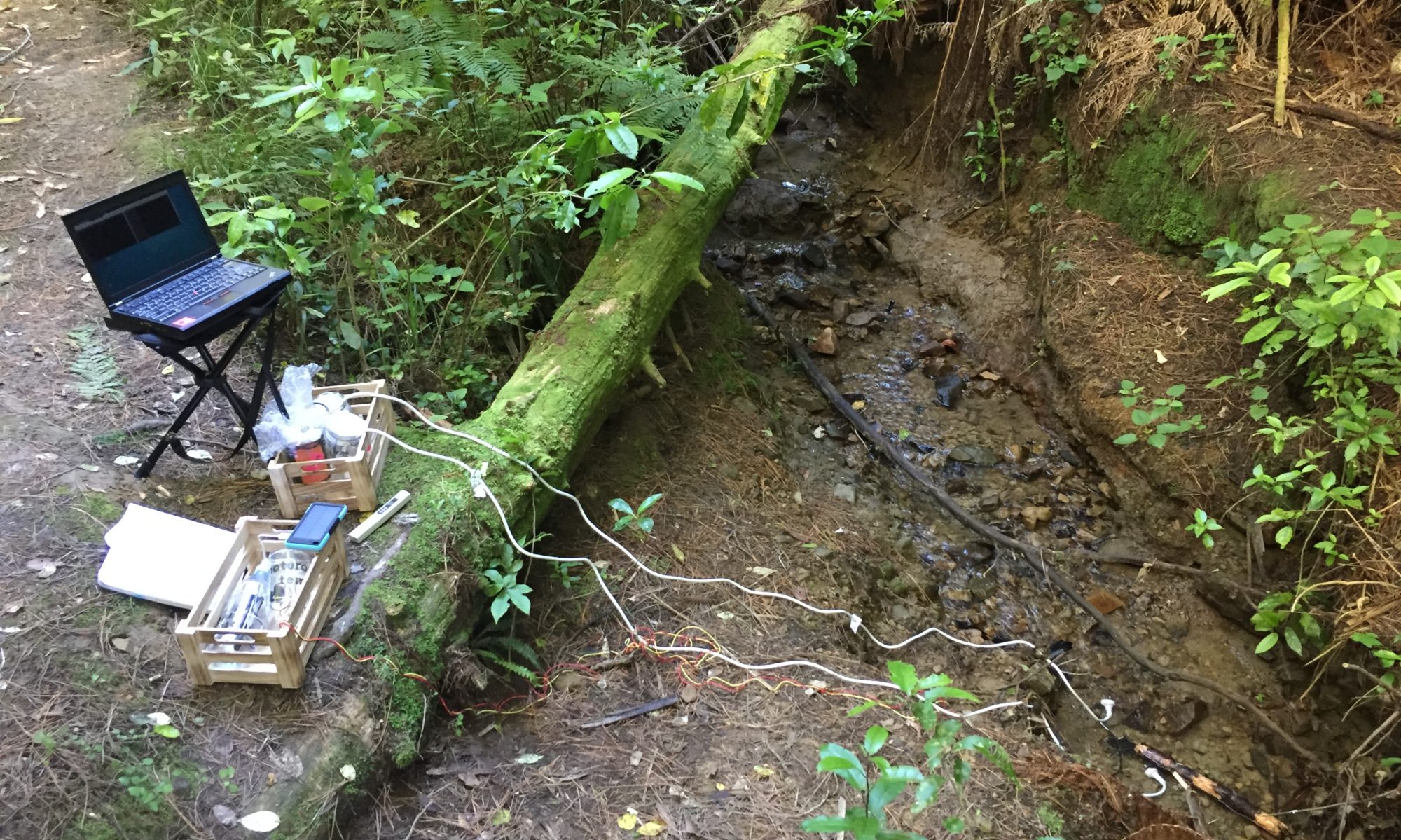
With this revised prototype I aimed to create a better, more stable design by inserting the LED and the photocell through holes into the hose while improving the sealing of electrical components from the beginning. I also wanted to use a cable with the actual length for use in the field and chose an approximately 2m long stranded core CAT-5 cable.
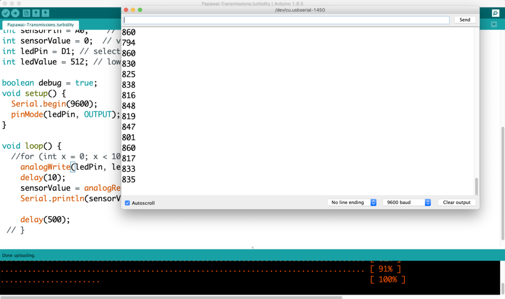
First I soldered the photocell to the green pair of cables and tested it with the code from yesterday.
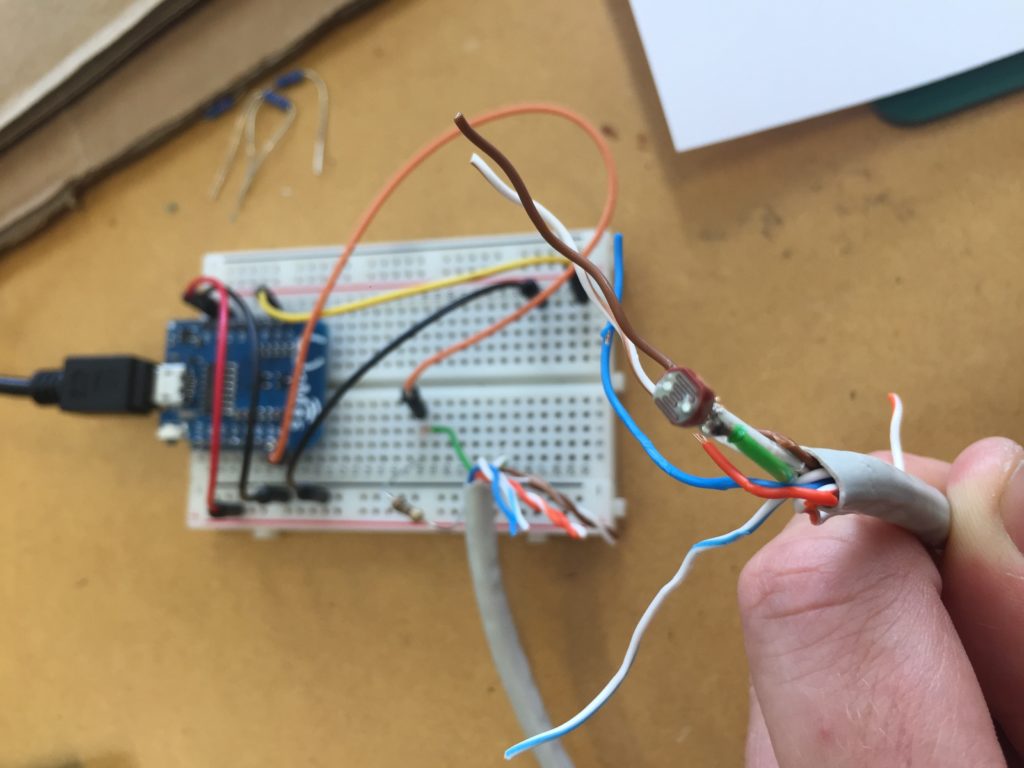
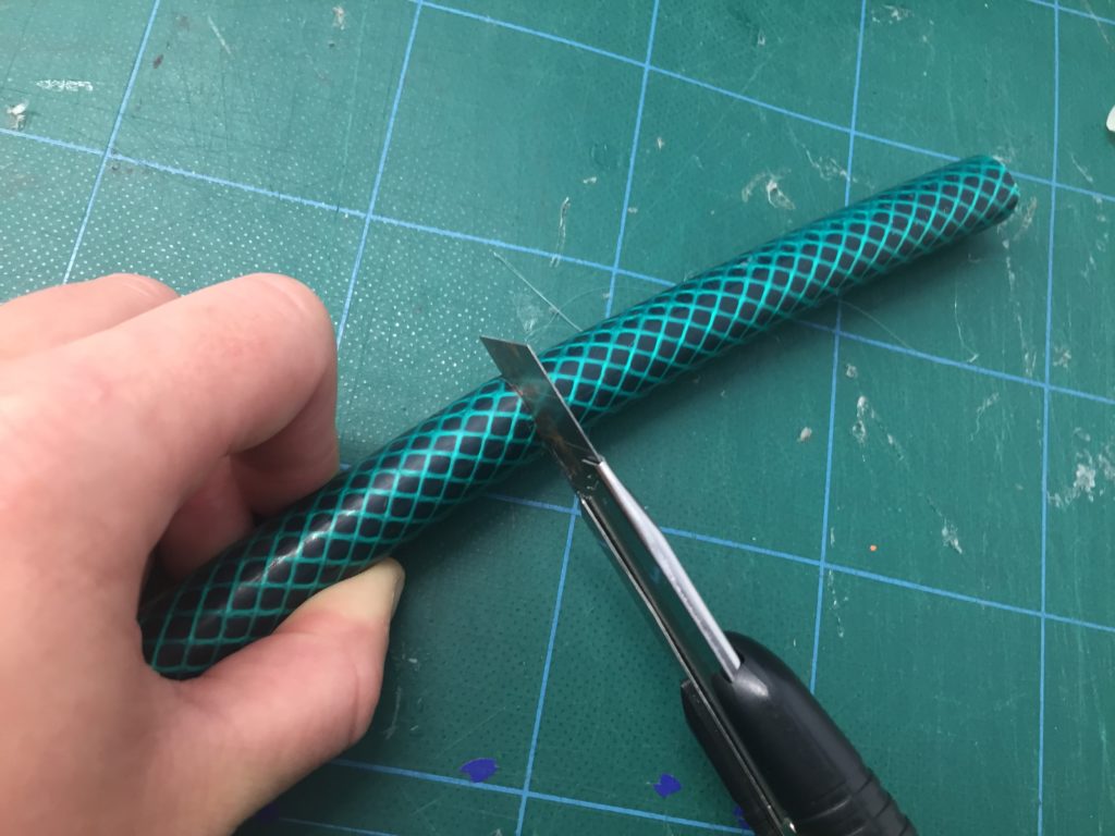
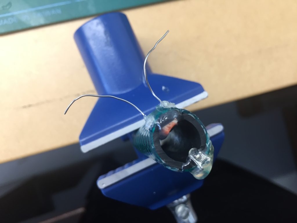
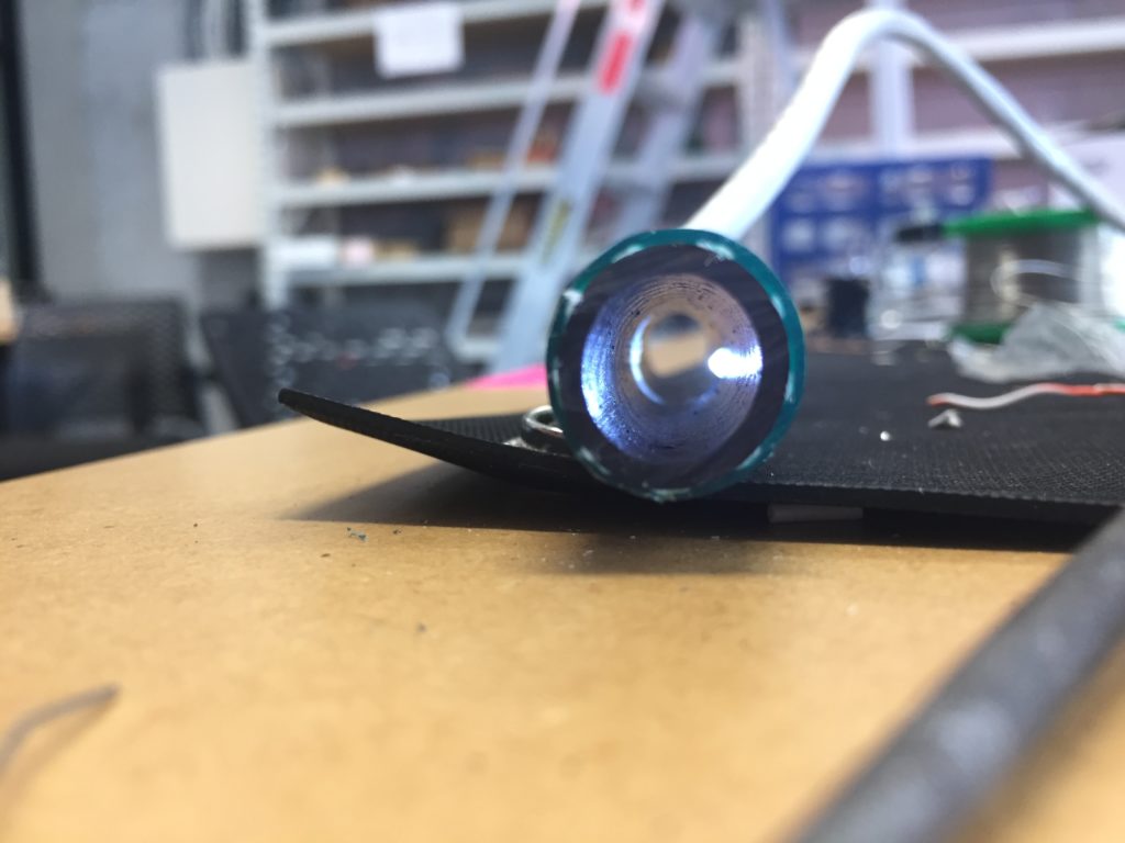
I drilled 5mm hole into the hose to fit the LDR neatly.
The 3mm LED requires a 3mm hole respectively. I drilled the 3mm through the 5mm hole to make sure the holes are nicely aligned.
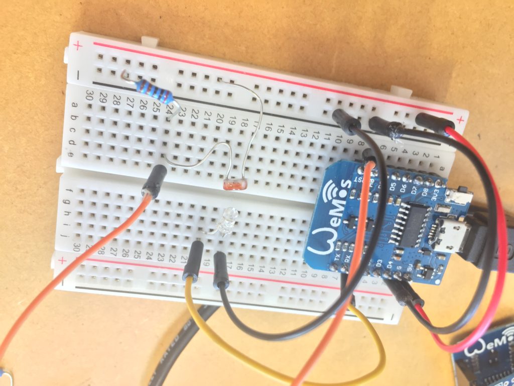
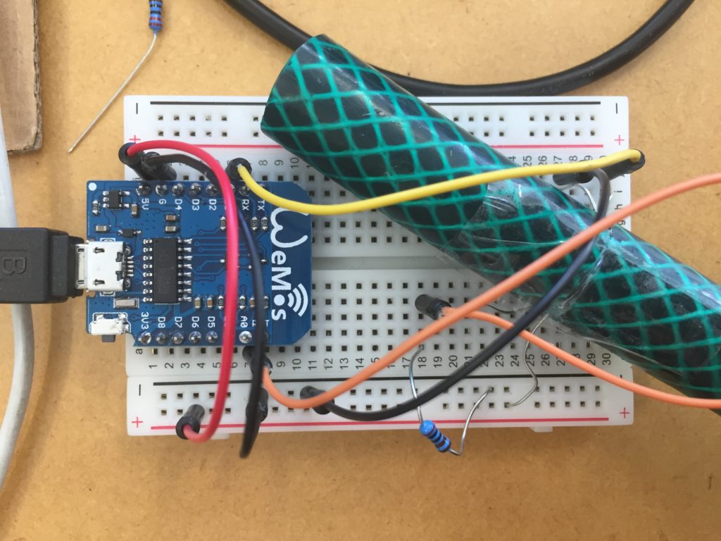
Reconnecting the wires with the breadboard from the previous prototype I ended up swapping the resistor to a 10k one which gave me more consistent readings when the LED was on half brightness.
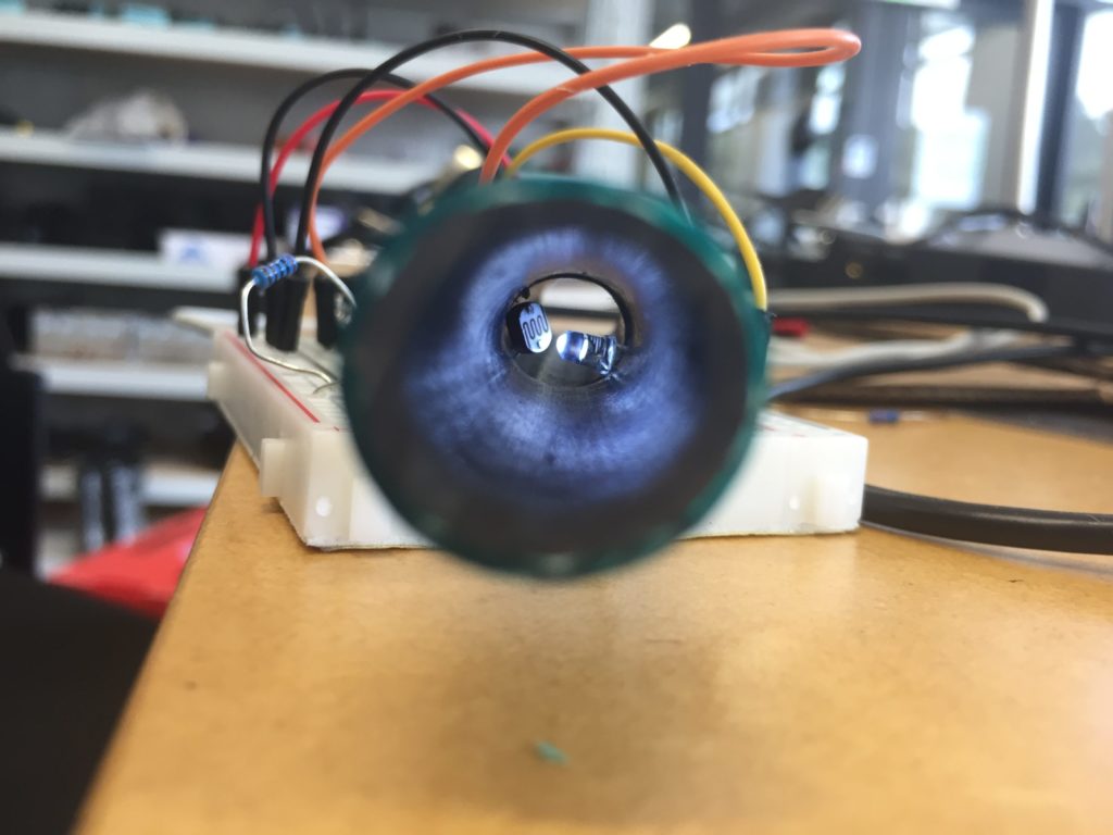
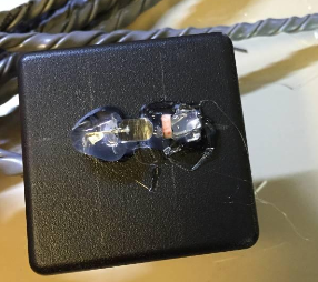
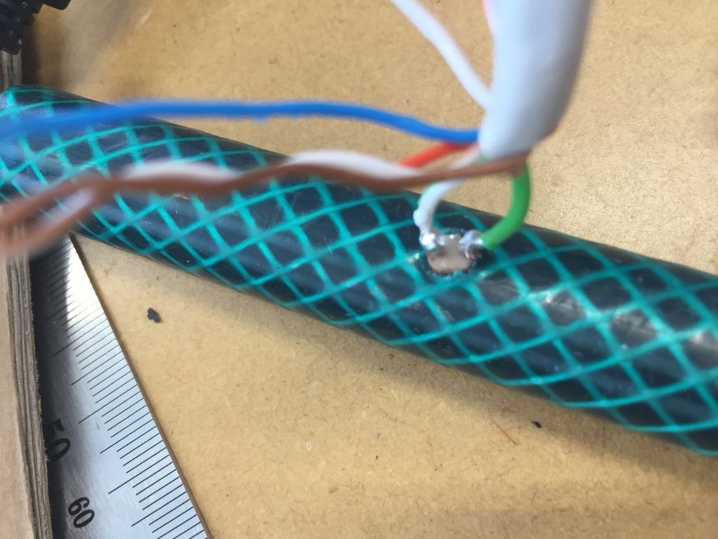
For the sealing, I purchased the All Clear sealant that I have previously used for waterproofing my hydrophone. As opposed to hot glue, this material stays flexible when dried out and doesn’t run the risk of getting brittle.
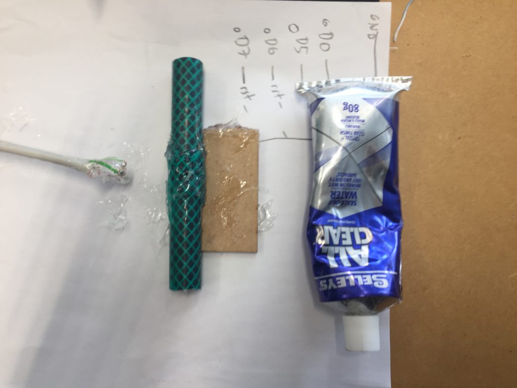
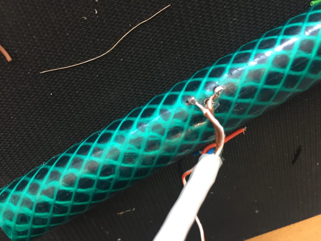
Unfortunately one of the LED solder points was not well done, and I only discovered it after having added the sealant. With the cable disconnected, this prototype is unusable in the field, but the process of building it helped me understand possible avenues for improvement:
The design with the components stuck through tight-fitting holes is cleaner but needs to be revised with waterproofing in mind.
Solder points need to be stress tested and – if necessary re-done – before adding sealant.
Cables need to be fixed into place before adding sealant. Sealing might need to be re-done in the 3D workshop with proper ventilation and safety gear as this might require the use of turpentine.
Sealant might need to be changed as it might not be ideal in combination with cables/electronics.
Component List:
Hardware:
- Computer with USB interface
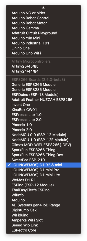
- Wemos D1 mini (know known as LOLIN
- 1 LDR
- 1 10k Resistor
- 1 3mm white LED
- Drill with 3mm and 5mm bits
- All Clear Sealant
Software
- Arduino
- CH340 drivers for your operating system
- Add ESP8266 to your Board Manager