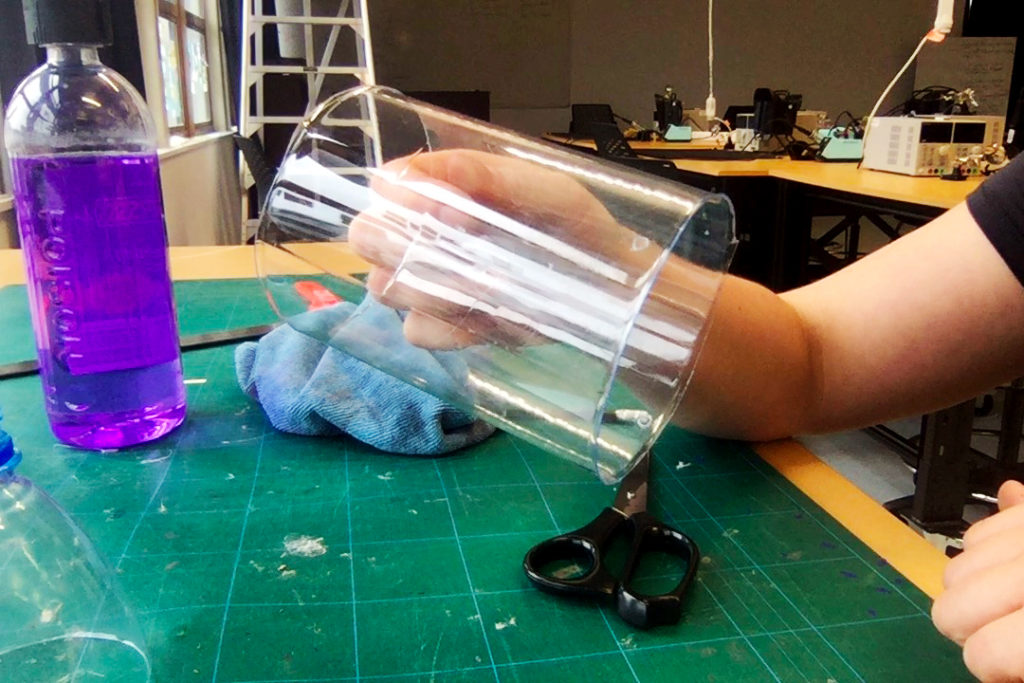
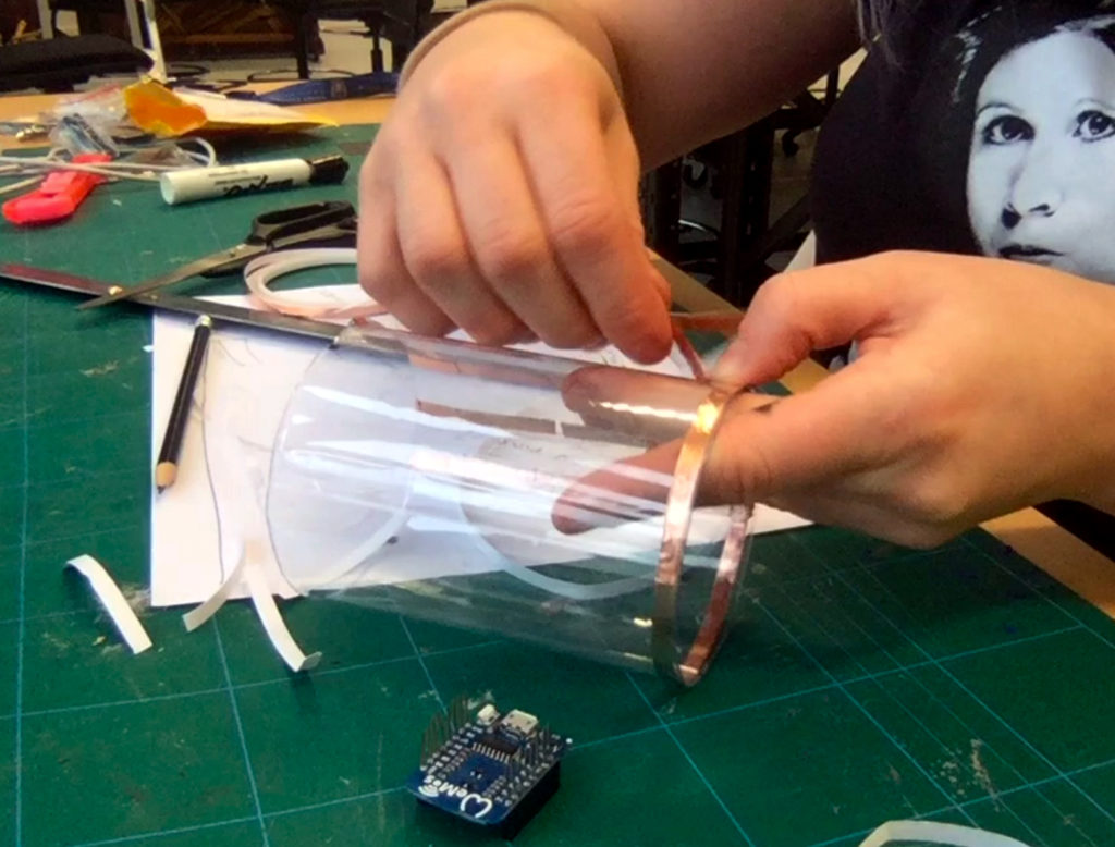
For this turbidity LED prototype, I wanted to test if I could use a transparent material instead of paper. This would make the microcontroller and the battery more visible and provide more literal transparency in the design.
Planning an designing the circuit
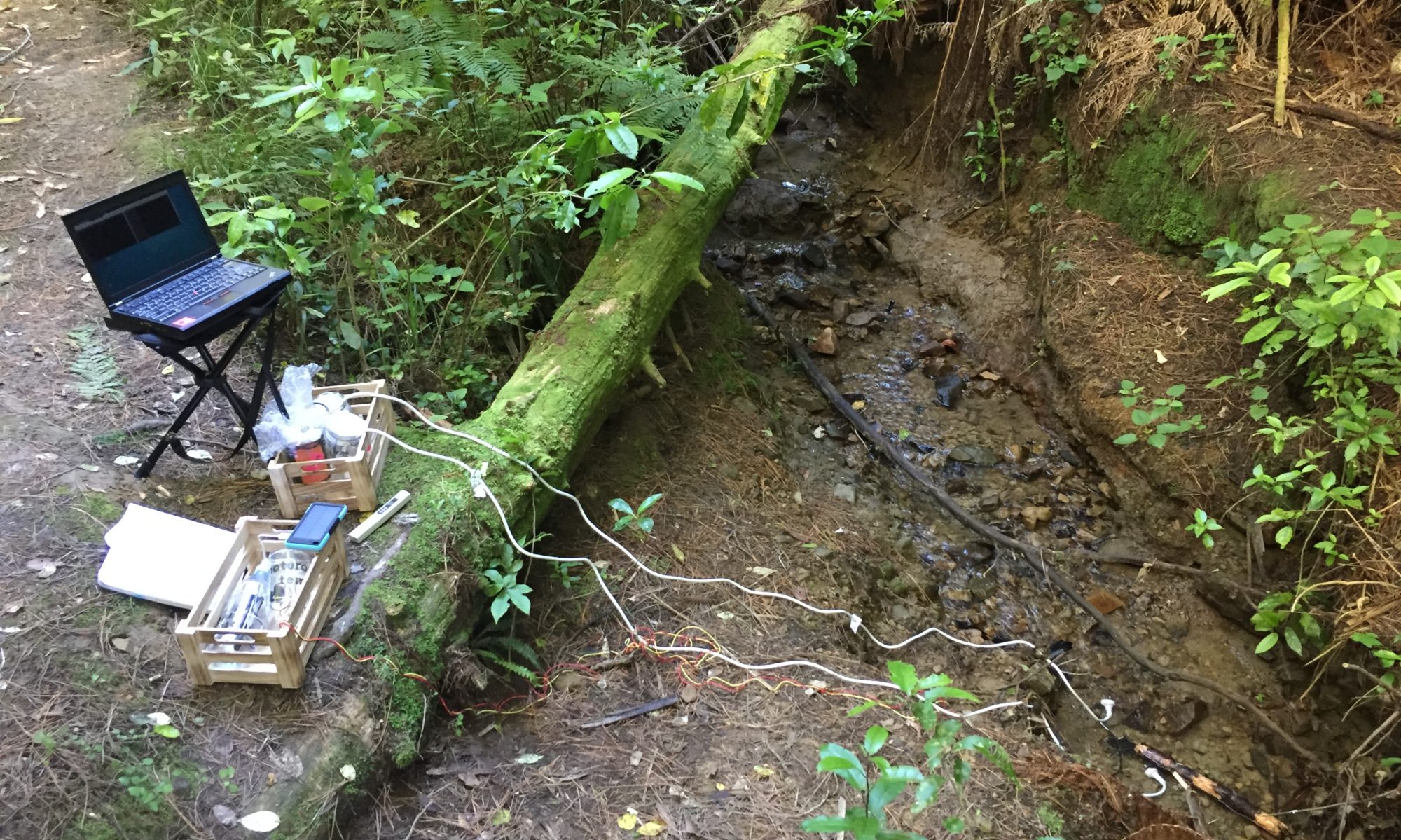
To avoid more plastic usage I recycled an old bottle from the Moturoa installation for this prototype. As a first step, I removed the Moturoa stickers and cleaned it with methylated spirits.
During my initial research I looked for known scales or visual indicators for turbidity but mostly found visual gradients.
My first idea for visualisation was to link the brightness of an LED to the sensor value. For example, if the LED is at full brightness this means the water is clear; if it is of low brightness the visibility of the water is low. An issue with this approach is, that it might be difficult for a viewer to estimate the maximum brightness of a single LED. Hence, a viewer might not be able to extract meaning from the displayed value.
A solution could be to have a reference LED next to the indicator LED that is always at full brightness as a comparative value. The indicating LED could also be faded on first to a complete maximum brightness and then dimmed to the readout value read by the sensor. This could work, but this method might be too complex and create confusion on how to understand turbidity.
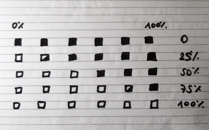
A simpler idea would involve visualising turbidity with an array of LEDs. If water clarity is at 100%, all LEDs are on. At 0% all LEDs are off, at 50% half of the LEDs are on (see sketch above). Using a variable brightness of the rightmost LED could work here to indicate a finer range of turbidity (25% would be one LED on maximum brightness and the
Assembly of the copper tape circuit
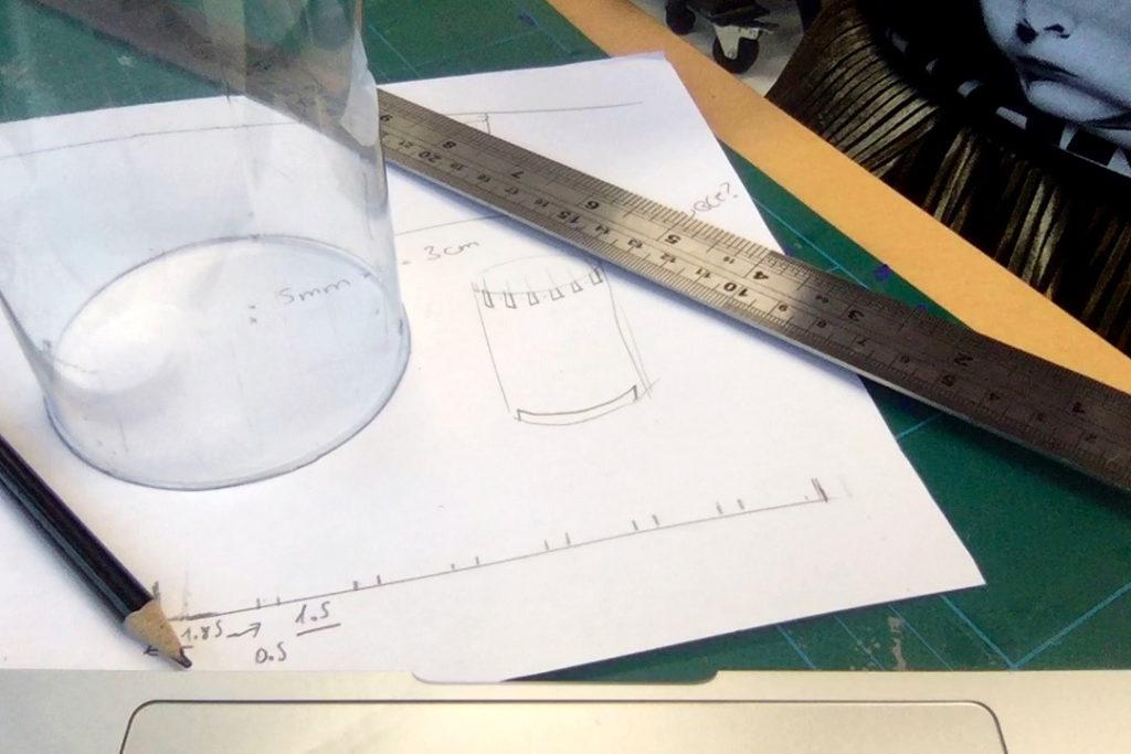
The plastic insert should fit inside a glass jar and it should be fitting into a variety of jar sizes. I place the six copper trails to the digital pins on the top of the plastic cylinder. I decided to line the bottom of the cylinder with one continuous piece of tape as ground (GND).
For this light probe, I chose blue SMD LEDs, mostly because I haven’t used this colour in any other probes so far. I apply some solder on the copper tapes first before placing the SMD on the circuit with a pair of tweezers. Then I melt one solder to tentatively put the LED in place before finalising the solder points on both sides. As anticipated, plastic and copper tape are not an ideal combination. Too much heat from the soldering iron melts the tape layer of the copper tape and lifts it off the surface (as with paper). The heat additionally shrinks the plastic and eventually deforms the entire surface.
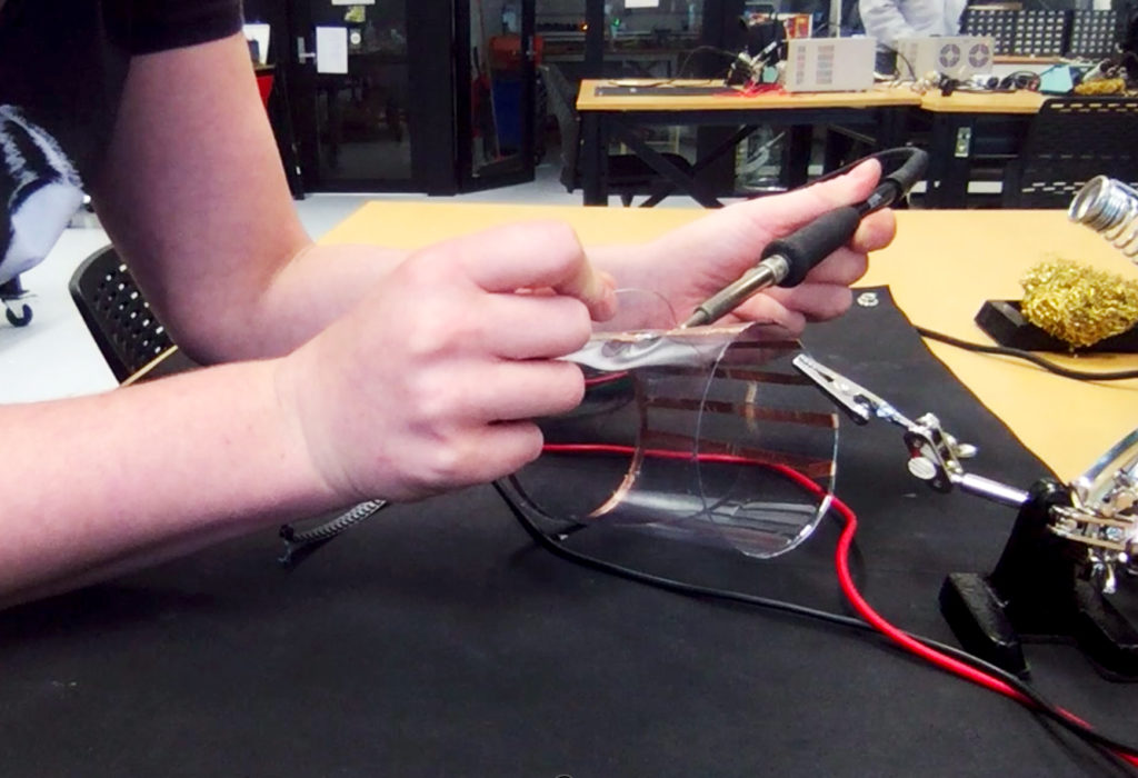
Before adding another LED I test every solder connection immediately by connecting a 3V power supply. This involves checking whether the solder point is good enough and if the polarity of the LED is correct. This batch of LEDs was easier to place on the circuit as they feature a clear polarity mark on the top.
To finalise the circuit I decided to solder copper tape ends together instead of taping them. Using sellotape to bridge copper tape ends has turned out to be a weak connection point in previous prototypes. This turned out to be a problem especially once I needed to bend the paper circuit to fit into the jars. The soldered connections are more stable and reliable. Unfortunately, the additionally applied heat and solder gave the GND copper tape a somewhat messy look.
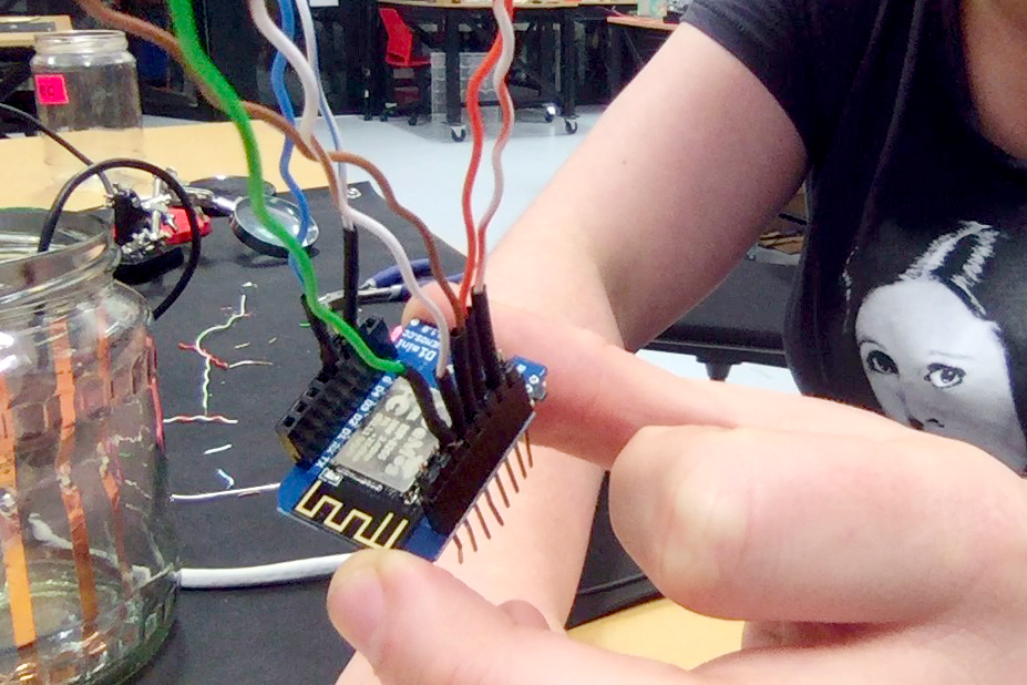
Connecting the circuit to the micro controller
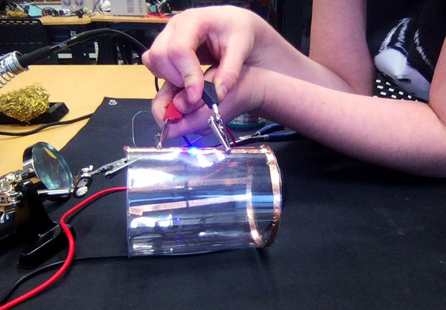
After placing the finished circuit into a glass, aesthetic details of the copper tapes become less obvious. The bright blue LED becoming the visual focus of the prototype.
The final soldering job involved attaching wires to the circuit that could connect to the WeMos D1 mini microcontroller.
I chose a piece of CAT5 wire and first soldered seven strands (6 digital pins plus 1 GND) to a row of pin headers to be plugged into the microcontroller. Once completed, I soldered them one by one to the copper tape circuit.
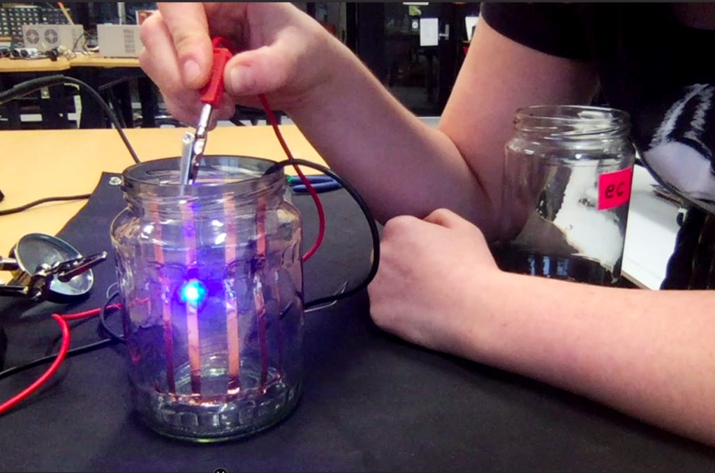
The assembly of the electronic components of the prototype