Turbidity Sensor III – One more time

The next iteration of the turbidity sensor requires more thorough waterproofing from the beginning. Prototype I started as a simple proof-of-concept of the component combination ( LED, LDR in a garden hose enclosure) and had no consideration of waterproofing. After that, the focus of Prototype II lay on improving the initial design’s lack of water-proofing and adding long cables so it can be eventually tested out in the field.

Part I: Components, cables and heat shrinking tube

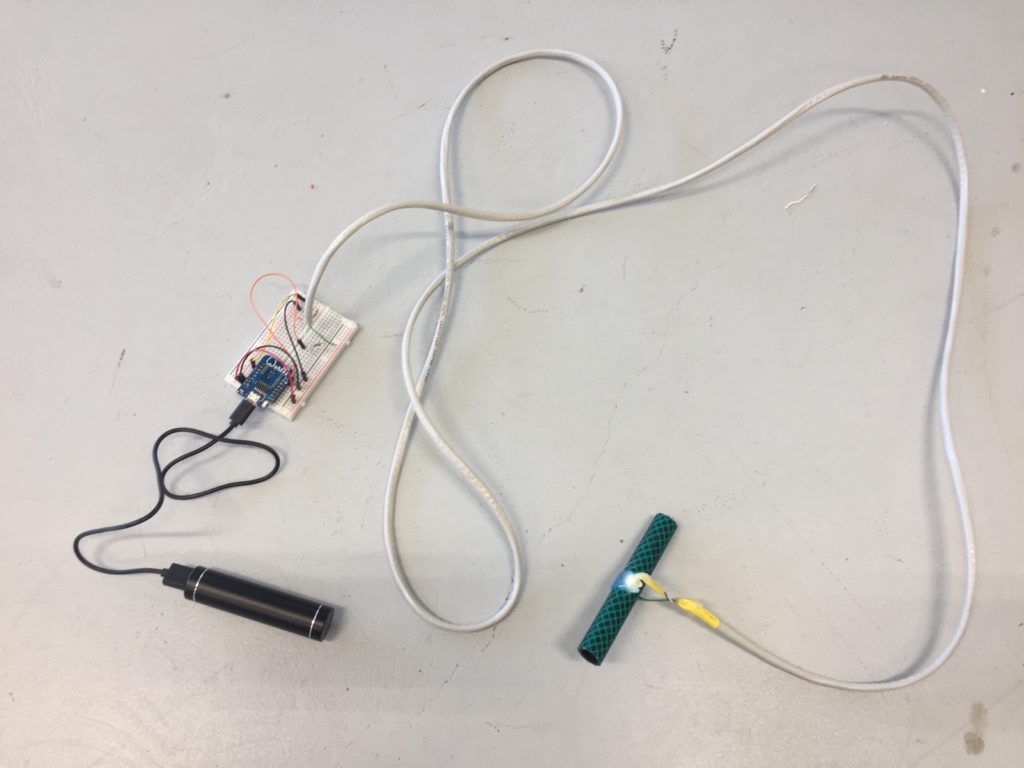
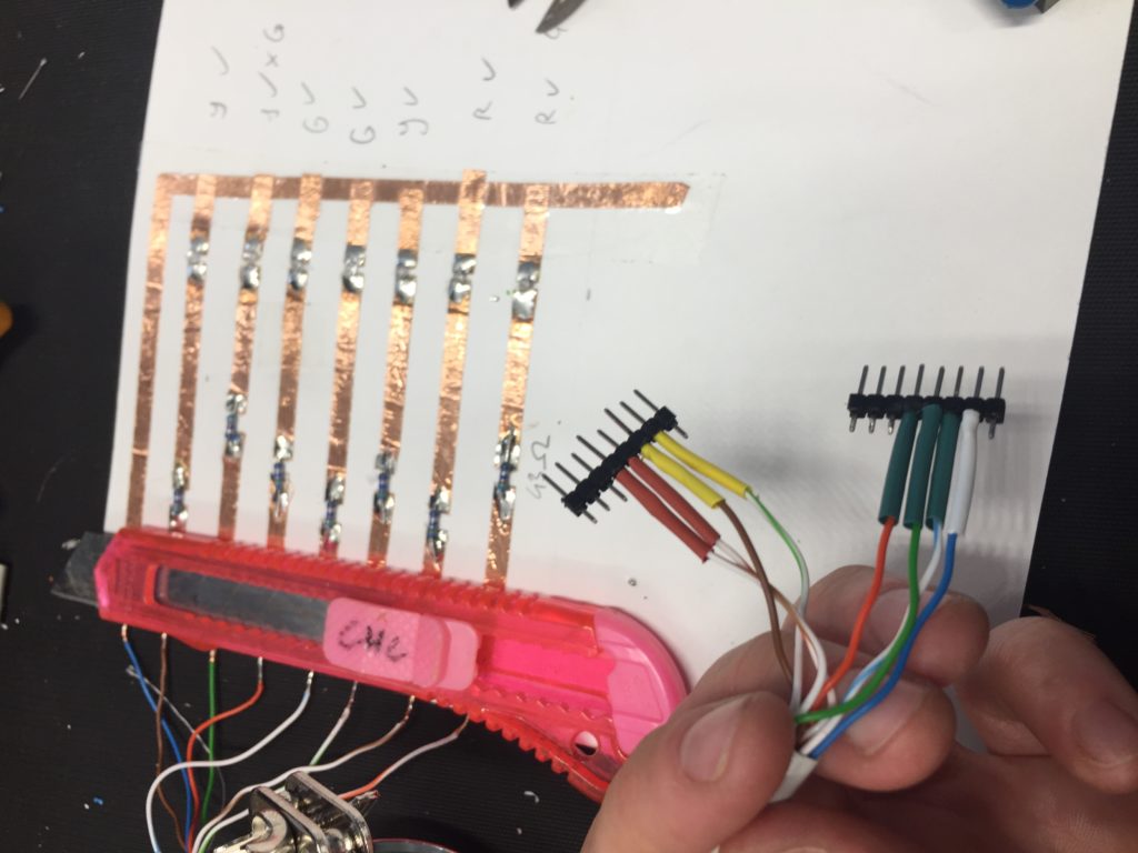
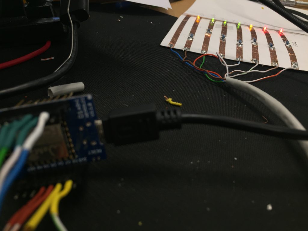
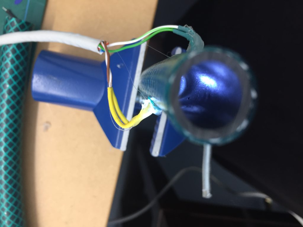
For this turbidity sensor design, I used an approximately two-meter-long stranded core CAT-5 cable to connect my white LED and my LDR to my Wemos D1 board.

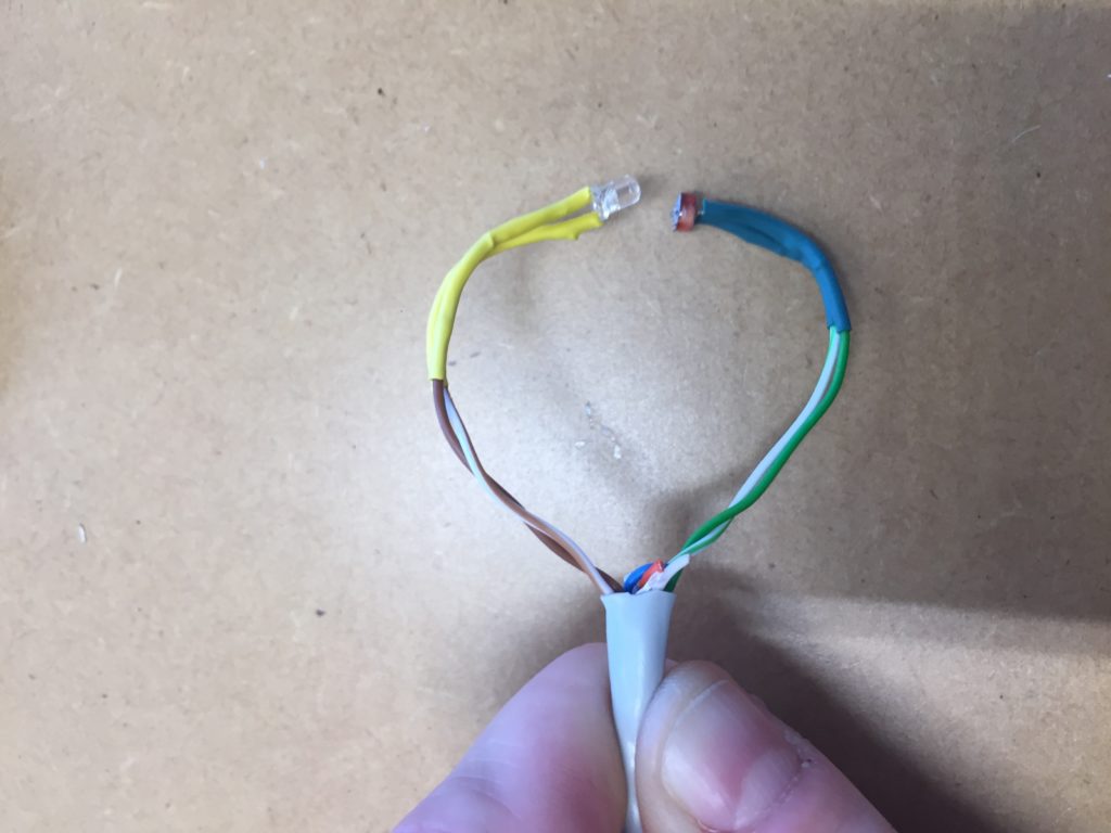
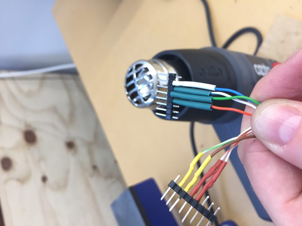
After assembly, I immediately sealed the components that eventually get submerged into the water with heat shrink tubing (yellow for the LED, green for the LDR).

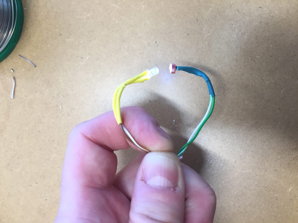
My first attempt at running the test code with the components through the two-meter-long wire went well. I tested the incoming values roughly by concealing the LDR with my finger.

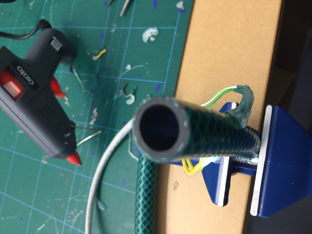
Part II: Housing the components in the “test tube.”

Similar to the previous prototype, I cut a new 10cm piece off the garden hose and drilled two opposing holes of the size of the components in the centre. To attach the LDR and the LDR I used hot glue only this time. The reasoning behind this is that hot glue has a much shorter drying/hardening time than the All Clear sealant. This allows an efficient applying of layer after layer within a relatively short period. The sealant ideally requires overnight drying which means assembly would span several days instead of hours.

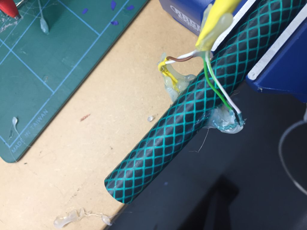
The work with hot glue is messy and requires diligence. Therefor, the purpose of the first layer is to attach the components to the hose and make sure they are facing each other correctly.

After the first layer has been applied I test that the components have not been damaged in the process of hot glueing. The incoming values look good so far, but I am not entirely happy with the design. It is quite hard to apply hot glue around the components evenly. I already spot some small grooves in the glue that could cause some leaks later on.

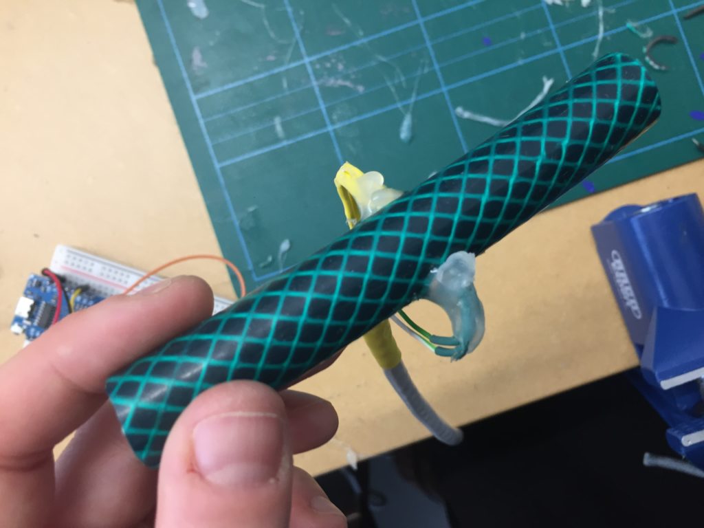
Part III: Dear hot glue, please protect my components

While applying the next layer of hot glue, I have already made peace with the fact that this probe is going to look very odd. Basically, I am looking at a small dark-green piece of garden hose attached to a long cable with semi-transparent blobs of glue. I also notice that the wire close to the components appears to be under strain caused by the angle the components are attached to the hose. I should have immediately bent the connectors at a right angle to avoid this oddly shaped glue blob altogether.

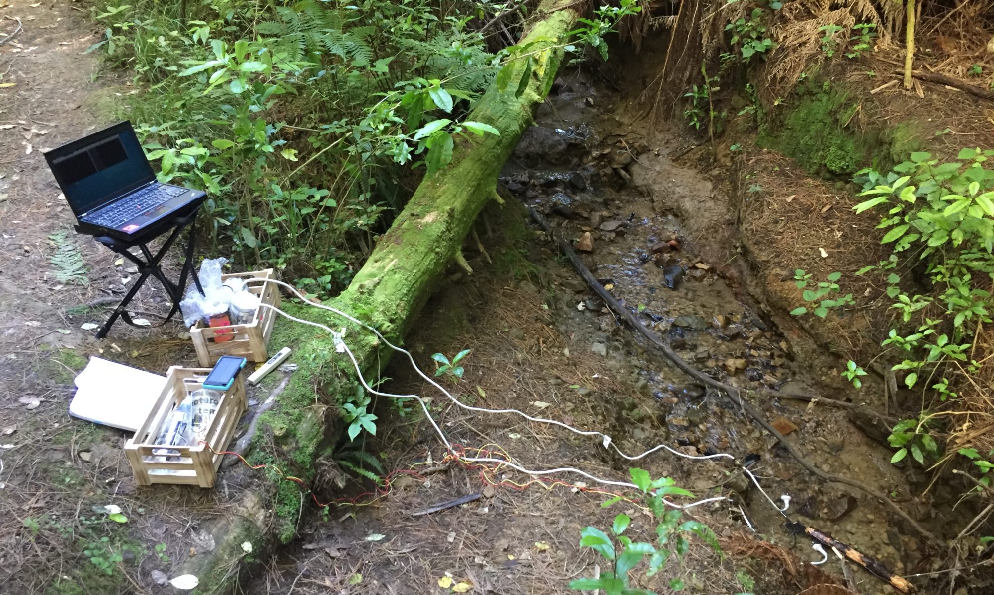
Despite the aesthetic shortcomings of this turbidity sensor design all components seem to be working, and I am ready to compile a version that sends data wirelessly via the MQTT network so I can safely test the design in an underwater setting, without the need of a laptop attached to any submerged components.

References
donblair. (2015, August 25). Turbidity 001. Retrieved January 18, 2019, from publiclab.org/n/12168
Kelley, C., Krolick, A., Brunner, L., Burklund, A., Kahn, D., Ball, W., & Weber-Shirk, M. (2014). An Affordable Open-Source Turbidimeter. Sensors, 14(4), 7142–7155. https://doi.org/10.3390/s140407142
NIWA. (2008, December 17). Training notes. Retrieved January 28, 2019, from https://www.niwa.co.nz/our-science/freshwater/tools/shmak/manual
/15trainingnotes
Open Water Project. (n.d.). Open Water Project. Retrieved January 28, 2019, from https://github.com/OpenWaterProject

Temperature visualization: Part II

The design for the temperature visualisation is based on the concept of the previous paper circuit for the EC probe but uses coloured LEDs that indicate the water temperature in relation to stream health, as listed in the SHMAK manual by NIWA (2008). The idea for using cardboard and copper tape for these prototypes is inspired by the work by Jie Qi (2012) and the High-Low Tech Group at MIT Media Lab (2012).

For finishing the circuit, I need to add resistors to the design as they have a smaller forward voltage than the white LEDs I used in the previous design. Using Ohm’s law, I calculated that 43 Ohm resistors are a good choice for all three colours.

After all the LEDs are lighting up when tested with a constant 3.3V output from a desk power supply, I use a Cat5-cable to connect the paper to two sets of header pins so I can test the work with the WEMOS D1.


Here you can see me testing the connectivity of components on bent paper. It appears that the angled copper-tape connections are the most fragile element of the design, especially the bent overlap that I have taped down with sellotape.

After powering the circuit with the desk power supply once more to test whether the LEDs still work with the cable bridges I add header pins to the end of the cables to provide a stable connection to the Wemos D1 mini microcontroller. I use colored heat shrink at the end of the header pins to identify cables with the respective LED color for more clarity if  debugging is required later.

The next step involves addressing all LEDs correctly with the Wemos D1 mini.

I had previously noted down the temperature ranges from the SHMAK manual (NIWA, 2008) and also added all values to the header comment of the testing code for easier reference later. This information also contains the colour of CAT5-wire strand, the digital pin connected, and the range of temperature as per SHMAK kit and the colour of LED (red/yellow/green) used to represent each state.

After some bugs in my code addressing all LEDs correctly (I ended up using digital ports D1–D8) I finally got all LEDs working with a simple looping sketch.

// Kaituhituhi-rua prototype - temperature

// blue wire - G

// brown wire          D7 - <5°C – 5°C - fair:5 (yel)
// green wire          D4 - 5°C – 9.9°C - good:8 (grn)
// orange wire         D2 - 10°C – 14.9°C - excellent:10 (grn)
// blue/white wire     D4 - 15°C – 19.9°C - good:5 (grn)
// green/white wire    D8 - 20°C – 24.9°C - fair:5 (yel)
// brown/white wire    D5 - 25°C – 29.9°C - poor:0 (red)
// orange/white wire   D6 - 30°C< - poor:-5 (red)


// LEDs
int ledPins[] = {D1, D2, D3, D4, D5, D6, D7, D8};

int ledState[8];

unsigned long previousMillis = 0;

const long interval = 1000;

void setup() {
  for (int p = 0; p < 8; p++) {
    pinMode(ledPins[p], OUTPUT);
    ledState[p] = LOW;
  }
}

void loop() {
  for (int c = 0; c < 4; c++) {
    for (int p = 0; p < 8; p++) {

      digitalWrite(ledPins[p], HIGH);
    }
    delay(500);


    for (int p = 0; p < 8; p++) {

      digitalWrite(ledPins[p], LOW);

    }


    delay(500);
  }

}

Next, I cut the paper into a smaller size and test how it fits in two different types of jars.

While fitting the paper into the jar I leave the microcontroller connected to evaluate how stable the solder and copper tape connections are. The power supply to the LEDs needs to remain stable while repeatedly inserting and removing the circuit from a jar. The LEDs indeed keep blinking which is a good sign. The smaller jar that was initially intended for the circuit has a pattern on the top and bottom of the glass which diffracts the LEDs and might make it hard to read.
The taller jar is clearer which makes it easier to see the LEDs, but from an aesthetical point of view, the circuit paper would have needed to be cut a bit larger to neatly fill the height of the jar.

In the end, I decide that both jars are suitable from a technical and practical perspective. The final choice of enclosure needs to be made after testing the prototype with the final code, showing only the LED of the respective temperature zone on.

High-Low Tech Group, MIT Media Lab. (2012, August 21). Paper circuits. Retrieved February 27, 2019, from http://highlowtech.org/?p=2505
NIWA. (2008, December 17). Habitat indicators of stream health. Retrieved February 27, 2019, from https://www.niwa.co.nz/our-science/freshwater/tools/shmak/manual/9habitat
Qi, J. (2012). The Fine Art of Electronics: Paper-based Circuits for Creative Expression (Master of Science in Media Arts and Sciences). Massachusetts Institute of Technology, Massachusetts, NE. Retrieved from http://web.mit.edu/~jieqi/Public/Jie_Qi_MS_thesis.pdf