Turbidity Visualization – alternative design

In the first turbidity node design I re-used leftover plastic of one of the bottle designs as the circuit carrier and copper tape for connections. This proved to be tricky as the heat during soldering would distort the plastic and dissolve the glue of the copper tape, making it lift off the surface and weaken the connections.

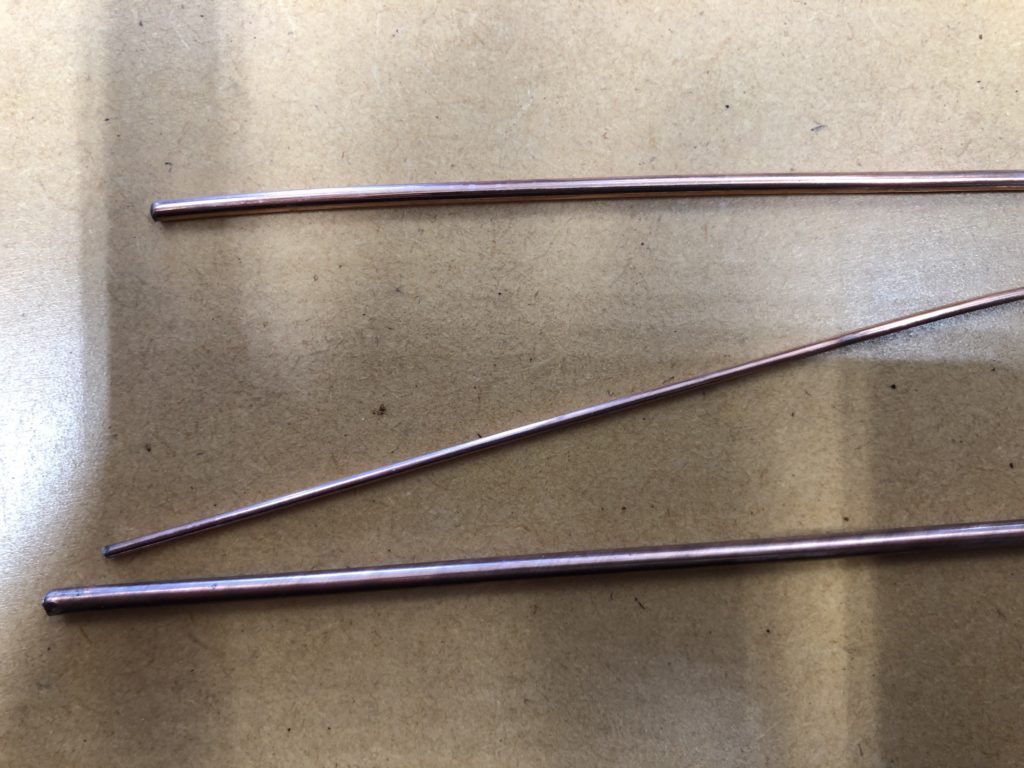
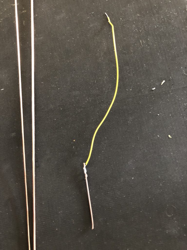
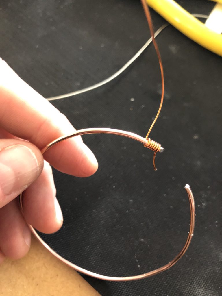
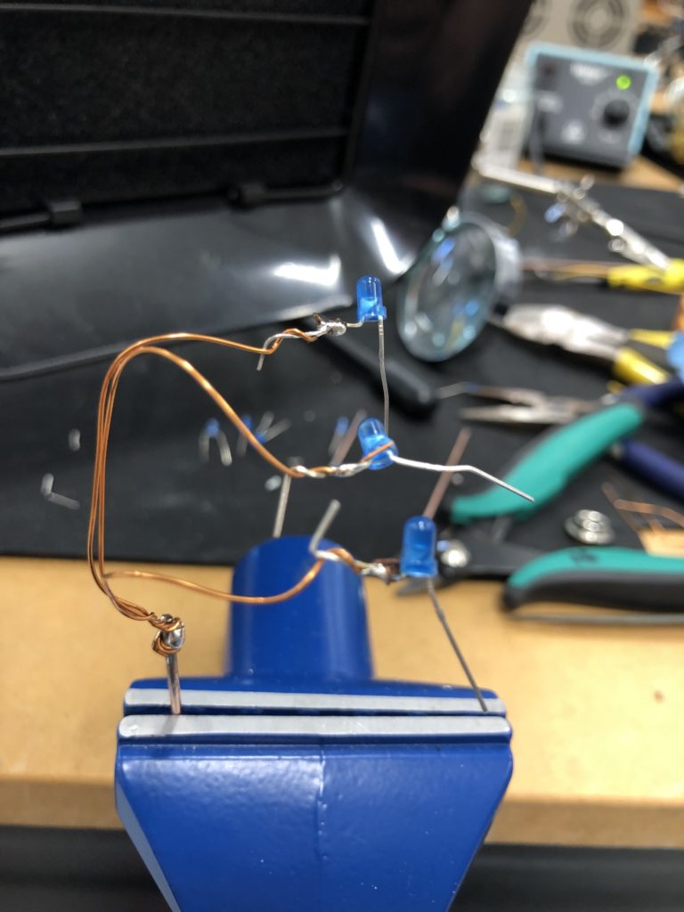
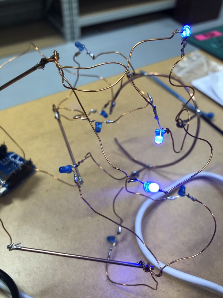
In a new attempt to provide a seamful design, this new prototype uses copper coated welding rods and copper wire as conducting elements and at the same time as structural element. This means the circuit would not require a surface, such as paper or plastic, but would only consist of conducting copper elements. For a first test I used a 1.2mm rod and experimented with soldering various wires and components to the rod. Soldering wire to the copper rod works well after removing the oxidation layer with sandpaper. The enameled copper wire also only solders well after sanding, which is time consuming when many components are involved. The advantage of this, however, is that the 3 dimensional circuit is less likely to be short-circuited, if parts accidentally touch – except for the conductive elements of the LEDs and the solder points.

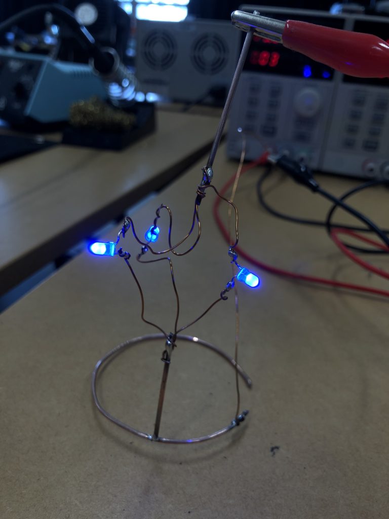
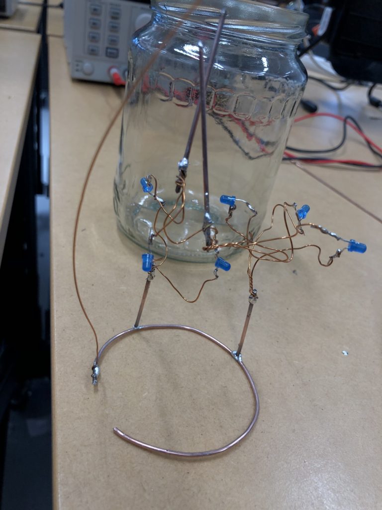
I envisioned the test design to contain a set of 3 addressable LED sets that fit inside a glass jar. I bent the Ground wire into a circular shape to act as a base for the circuit which will connect to a set of LEDs to be controlled by a Wemos D1 board. After a hopeless attempt to use SMD LEDs for this circuit I found that 3mm LED diodes are much better suited for this kind of circuit.

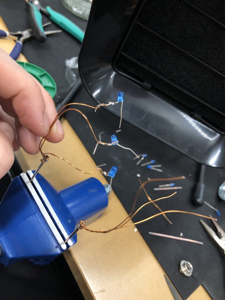
In the end, I connected a set of three LEDs to three individually addressable wires. The copper rod needs to be bent carefully with flat pliers while the copper wire bends into shapes very easily. This gives the final circuit a quite messy look and I am unsure the design in this form would be suitable to provide any meaningful visualization of the turbidity reading.
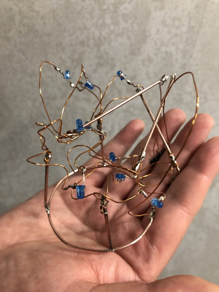
The circuit appears quite fragile, the copper wires can be bent and crushed in the hand which gives it quite a unique aesthetic when handheld. Once transferred into a glass jar, the intricacies of the circuit design fade into the background, and the bright blue LEDs, as well as the battery and the small circuit board, distract from the fragile wires. I programmed the board with a simple test sketch that loops through the three LEDs.
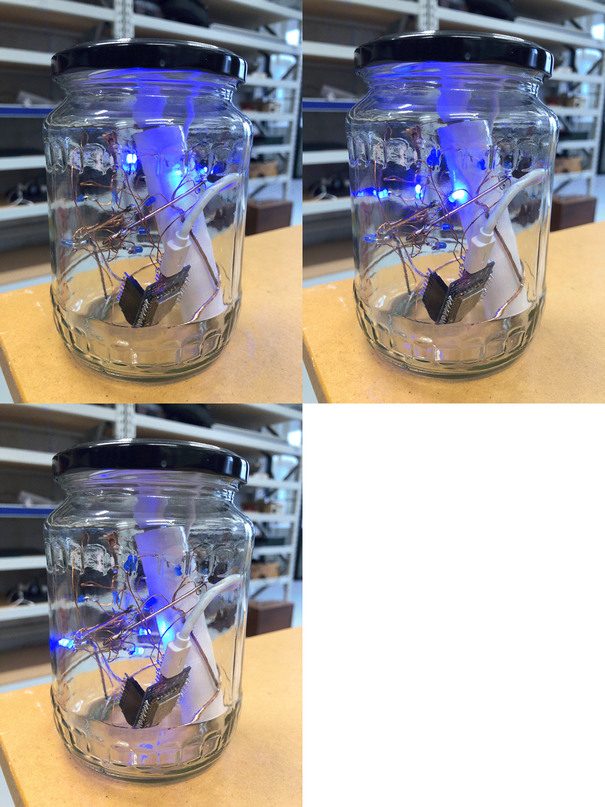
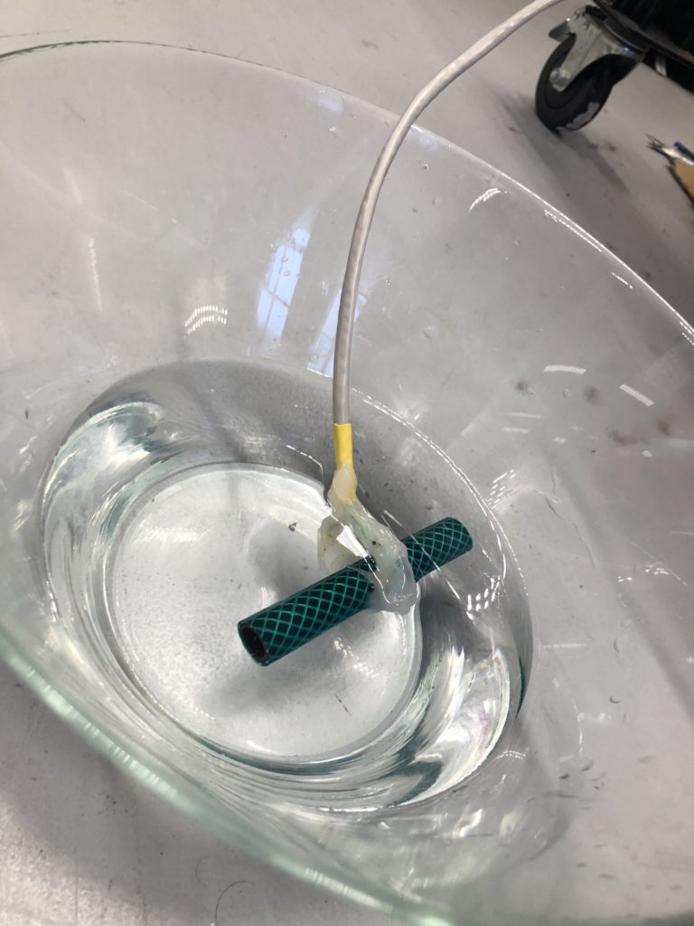
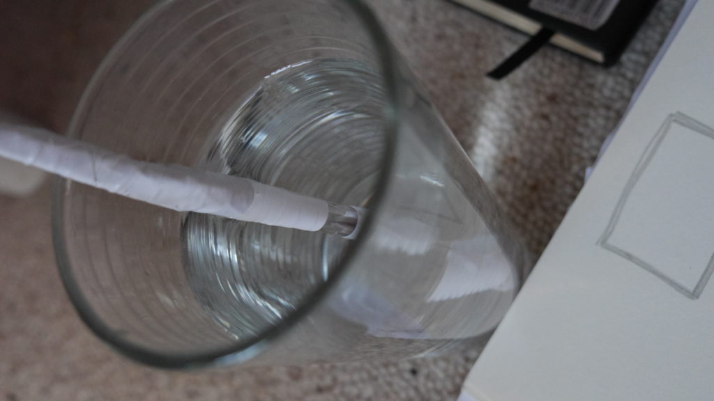
The next step involves connecting this design to the turbidity sensor through my local MQTT network. I submerge my turbidity sensor into a glass bowl filled with water to get more realistic sensor data readings for this test. Unfortunately, the circuit design appears to be tricky to be programmed, and only after a while am I able to successfully de-tangle the wires that must have short-circuited somewhere, causing the code to malfunction and print nonsensical glyphs in the serial monitor when I try to debug my code.

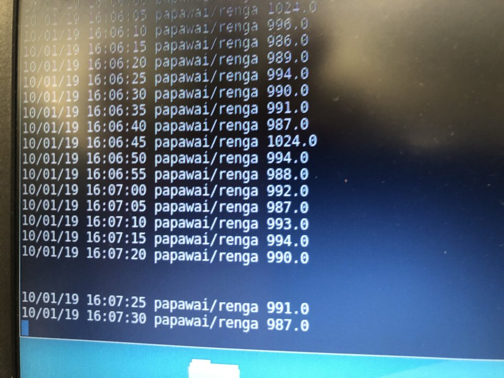
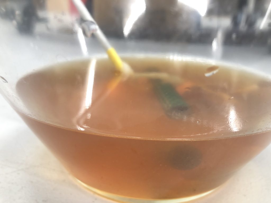
Once my LED node is properly connecting to the WiFi network and correctly receiving the sensor data I map the turbidity to the amount of LEDs being switched on. To achieve a more murky fluid for this test I add a teabag to the water. I notice that the value changes are not as extreme as i would have hoped for and assume that a different resistor, perhaps a trimpot, would help to get more accurate data. Another issue with the sensor data is jumpiness. This could be because the LDR is just not suitable for an accurate measurement, or perhaps the sensor design is not waterproof and hence unreliable. Perhaps the code could be improved by measuring a running average over a couple of miliseconds, instead of measuring the brightness only once sand immediately transmitting this data.

Despite issues with the quality of sensor data, I learned a lot about the feasibility of this circuit design. While the copper wire gives the circuit a unique, messy look that I generally like, it is unsuitable for providing an easily understandable visualization of sensor data. Using only copper rods in combination with 3mm LEDs could work with a refined sketch on how to accurately map the sensor reading to an arrat of LEDs.
Giving voice to the stream: An audio node part I

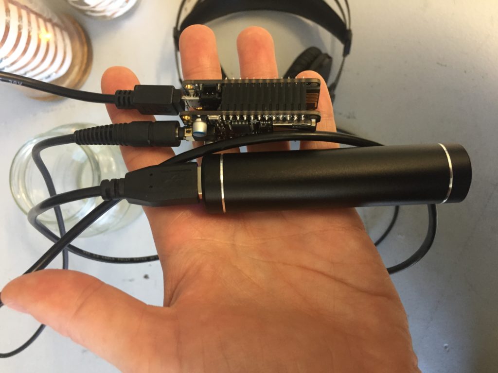
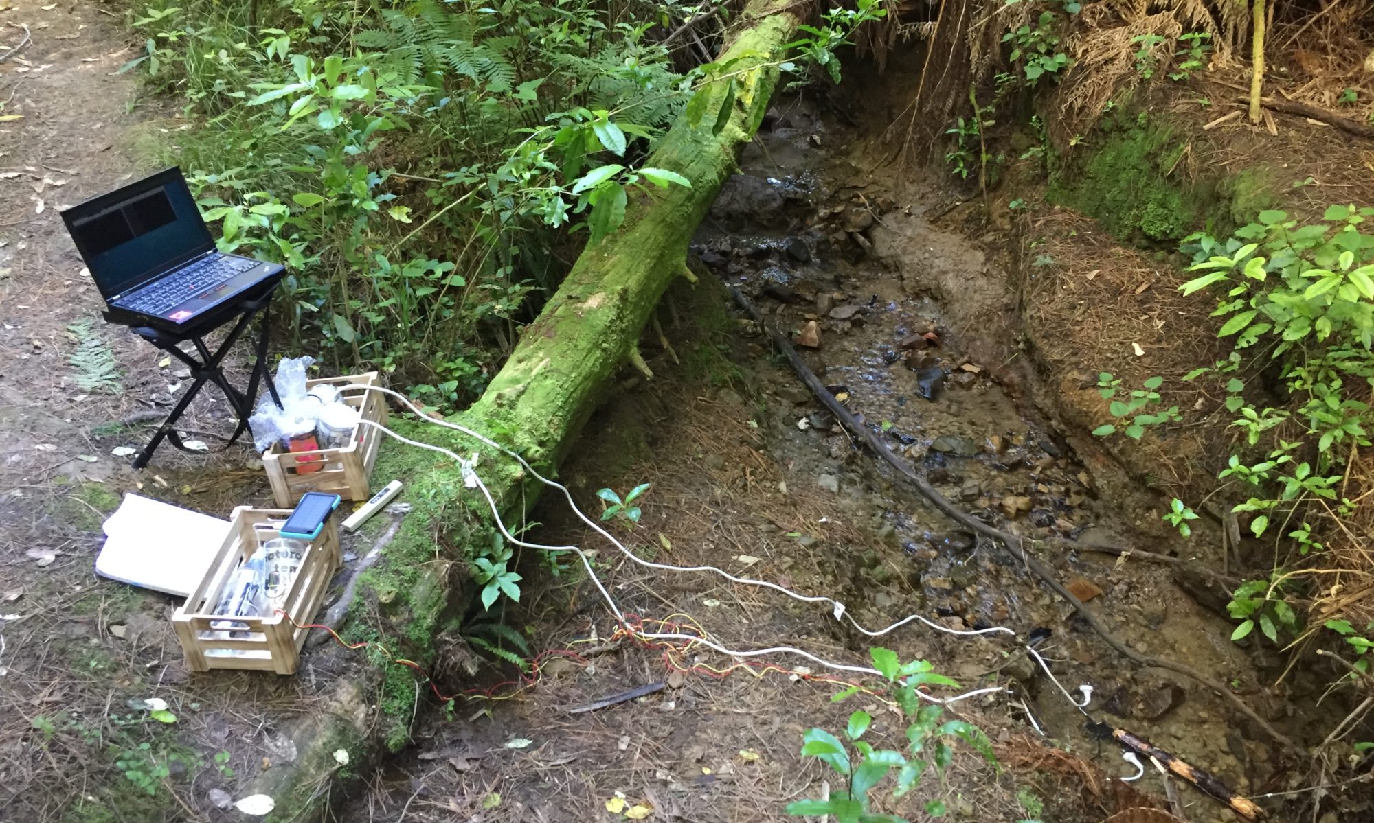
Several participants in my design evaluation interviews indicated the interest in having audio as a medium to access the stream sensor data. As a result of this, I looked at options to use the ESP8266 chip in combination with a simple audio interface. I found some research on using the Wemos D1 for sound applications, a previously purchased microcontroller, the Adafruit Feather Huzzah can be expanded with the Music Maker FeatherWing, which adds an audio interface with a headphone jack output which could be used as a standalone version in the field.

Setting up the Adafruit Feather Huzzah

The Feather requires you to install a USB-driver (USB to UART Bridge VCP drivers) to work with your operating system properly. Note: For this install you need to restart your computer.

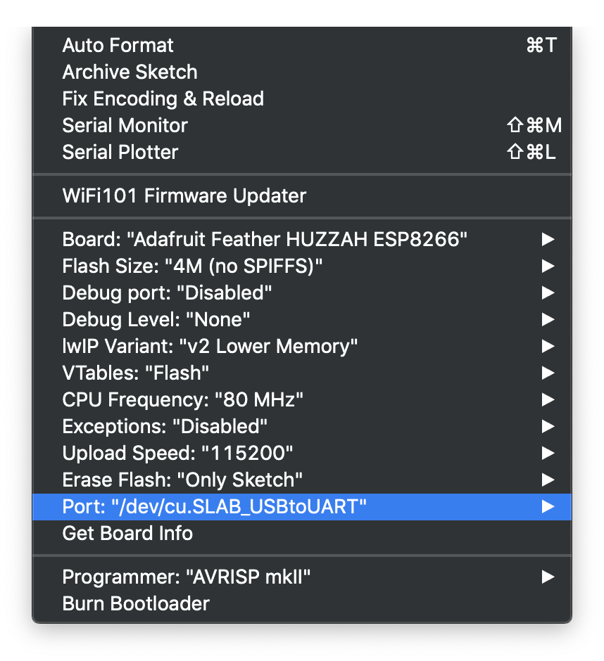
The Huzzah is part of the ESP8266 board manager, which needs to be added to the Arduino IDE under via Arduino…Preferences…Additional Board Manager URLs…

If step one and two have been successful, the Feather should be ready to be programmed with the Arduino IDE.

Arduino…Tools menu showing correct Board and Port to work with the Feather

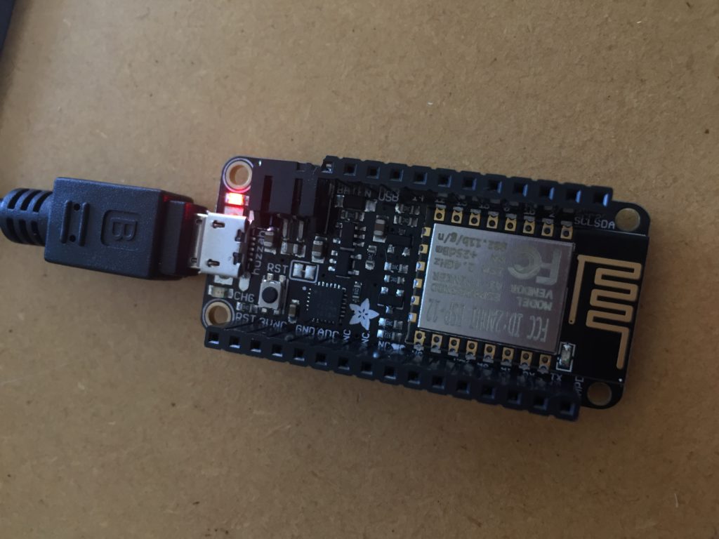
Success. The Blink sketch is running smoothly on my Feather.

    Feather Huzzah running the Blink script
Equipment Cost

I have ordered the Feather ordered at an earlier stage of the research project, but decided in the and not to chose it as the chosen as a central component of my project, mainly because of the price point (currently $33.00pp vs Wemos D1 $10.00pp on nicegear).

The Musicmaker shield adds another $36.00 to the sum.

For a complete audio player setup, an SD card (to store the mp3 files) and headphones are required. The MIDI setup does not require the SD card.

Adding the Audio Shield

Once the Musicmaker arrives I need to install some software as described in the guide by lady ada (2018):

  1. Install the library for the Adafruit VS1053 Codec Breakout (lady ada, p.13).
  2. Test the example code feather_player with two mp3 files on the SD card.
  3. Solder the MIDI jumper on the bottom of the board together and test the MIDI example.

So far so good.

Now I need to connect the Feather to my MQTT network and have audio play triggered by a callback.

After some fiddling with the code, I manage to play the test Ocarina scale from the example code when the EC sensor and the water temperature sensor transmit data across the network.

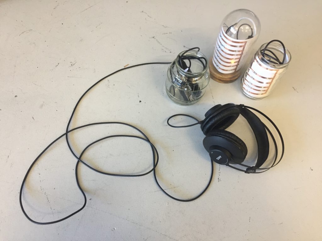
The audio jar stands now among two visual outputs. While it offers a different mode of access to the stream data, it also breaks with the convention of having one-on-one relationships between input and output nodes.

I also need to consider if the jar casing is the best choice for this node, and how an audience would access the data in the field. The node could be a hidden audio jack that participants can plug their headphones into, or headphones can be provided. Alternatively, I could use a small speaker to play the sound output and make the experience accessible to multiple users at the same time.

The opportunities for this extra node need to be tested and evaluated in the field.

References
adafruit. (2019). Adafruit_VS1053_Library [Arduino]. Retrieved from https://github.com/adafruit/Adafruit_VS1053_Library/archive/master.zip
lady ada. (2018, August 22). Adafruit Music Maker FeatherWing. Adafruit Industries. Retrieved from https://learn.adafruit.com/adafruit-music-maker-featherwing

DIY Electrical Conductivity: Trial and Error

EC Version 1: Pens, Nichrome and too much tape

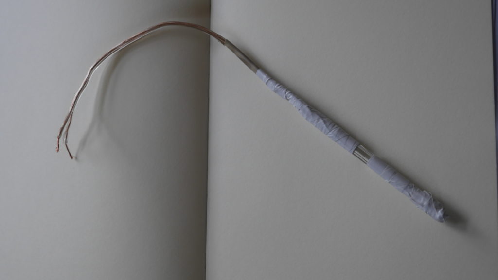
The first EC meter I built was based on the instructions by Practical Maker (2011). The probe involves two Nichrome resistance wire attached to an empty pen tube and covered with electrical tape.

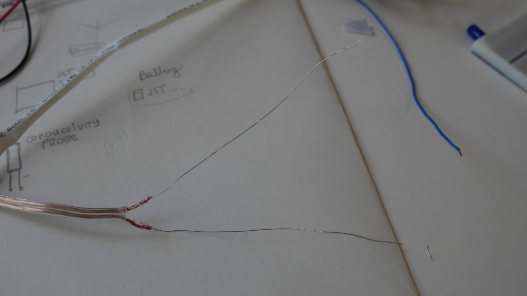
The Nichrome wires are soldered to stranded core copper wire from an audio cable and connect via a 10kΩ resistor to the analog input of a Wemos D1 mini. 

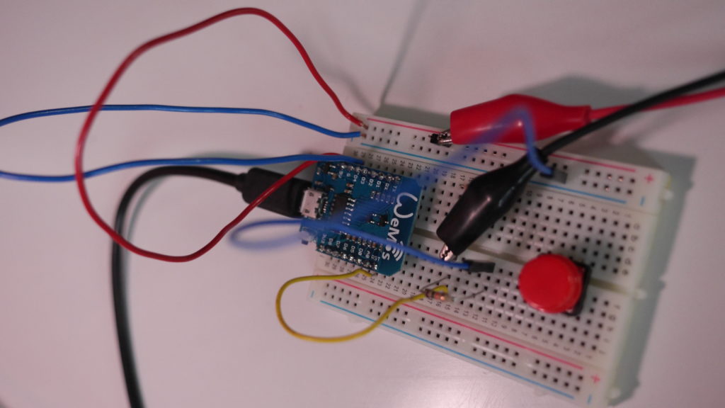
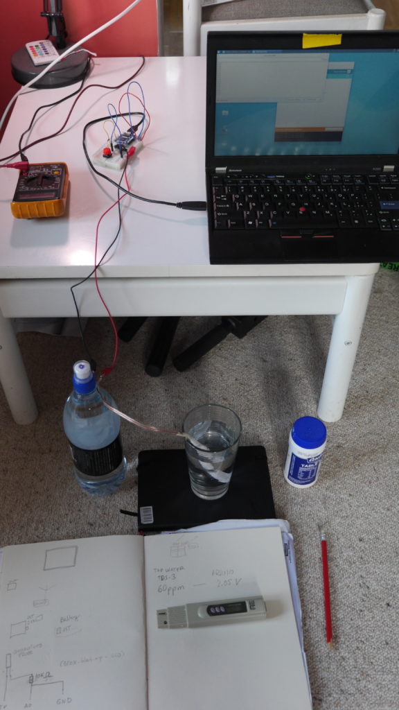
For testing I would use the Wemos D1 mini in combination with a small breadboard and jumper wires and header pins connecting to alligator cables to hook up my probe to the micro controller and my computer.

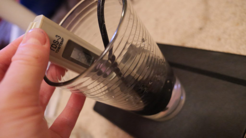
For the test setup I initially submerged the probe in a glass of distilled water. I would read out the voltage via the Arduino Serial Monitor and note the voltage value down in my notebook. I would also take a reading with my TDS-3 meter and note the value down next to the voltage. I would add a measured amount of salt to the water solution and repeat this process.

While the initial voltage readouts looked promising, the material assembly of the probe proved problematic and generated inconsistent voltage readings.

The final assembled design of the first unsuccessful probe


The electrical tape trapped water in between the multiple layers which would generate inconsistent readouts. The probe would also still show conductivity once I lifted the probe from the water solution, which would only slowly drip from the parts and also slowly lift and move the electrical tape. To sum it up, this probe design was not only quite complex and flimsy, but also unreliable in terms of readouts. This meant I needed to look for another solution. 

EC Version 2: Repurposing a wall plug

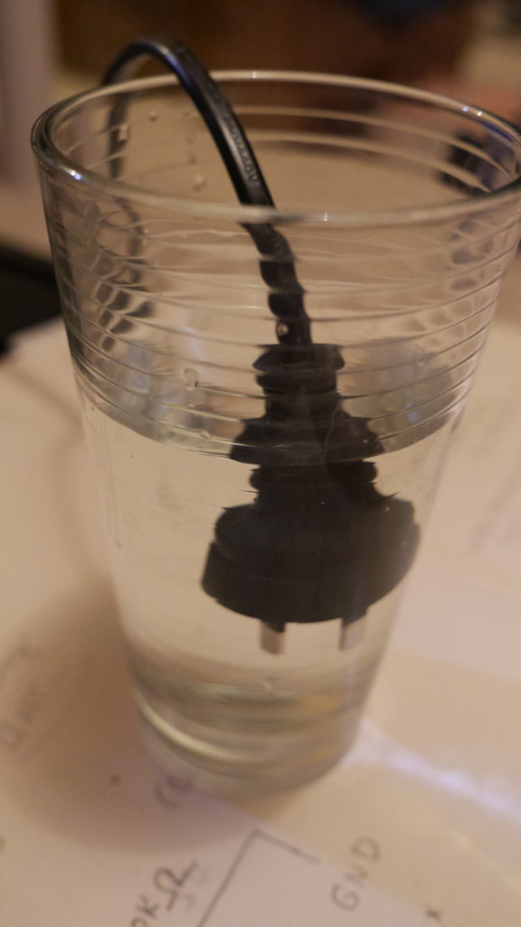
In a very detailed blog post Ratcliffe (2015) described how to build a EC meter for Arduino for $3. His solution involved repurposing a Type A Two Prong american plug. I took one old New Zealand plug and connected it to my previous setup.

The appearance of a power plug suspended in a glass of water looked very strange from the start. However, the initial tests showed that the plug was an easy, hassle-free way of generating reliable voltage readings alongside the TDS meter.

Practical Maker. (2011). DIY EC Probe. Retrieved from https://www.youtube.com/watch?v=0NPtmHdbW3k
 
Ratcliffe, M. (2015, September 4). Three Dollar EC – PPM Meter. Retrieved March 19, 2019, from https://hackaday.io/project/project/7008-fly-wars-a-hackers-solution-to-world-hunger/log/24646-three-dollar-ec-ppm-meter-arduino

Building a low-cost hydrophone

For this research I want to explore what kind of DIY electronics can amplify the voice of the forgotten streams in Poneke/Wellington, New Zealand. As a first device I want to build a hydrophone that can be used during fieldwork to record underwater sounds.

Hydrophones used in scientific research, for acoustic monitoring, such as for tracking marine animals, are relatively expensive and even DIY solutions feature costly elements (see for example Dawson, 2012). In low-cost DIY solutions old audio components, such as headphones or radios are re-used (e.g. digifishmusic, 2008) and made waterproof with silicone or hot glue.

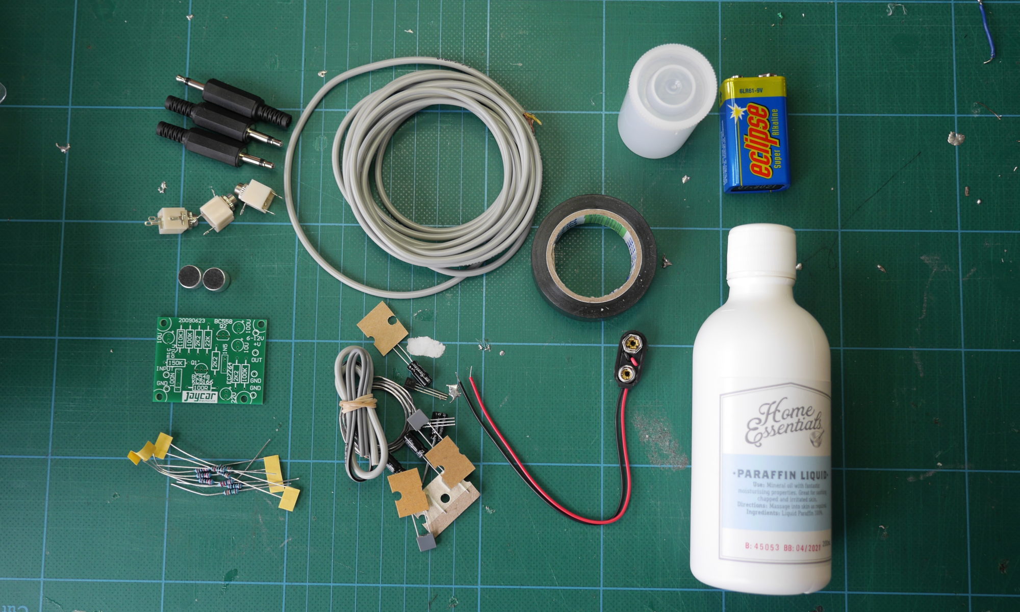
I decided to combine building a hydrophone based on two instructions. Both are based on using an electret microphone element as the primary component. In the instructions of Decker (2013) the element is enclosed in an empty film canister filled with mineral oil as a medium to optimize the hyrdophone. I chose this design for the first version following a suggestion on the Wellington Sonic Arts Facebook. The instructions by the University of Waikato (2011) feature a component list that is available in New Zealand.

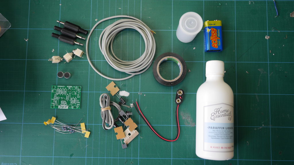
components used for first hydrophone prototype

Building the first version of the hydrophone took less than a day and involved researching the best possible option to be done within one day, sketching a schematic alongside a shopping list of necessary parts, planning the quickest route around town to buy all necessary parts and then 2 hours of soldering and assembling plus some extra time for testing and troubleshooting and documenting along the way.

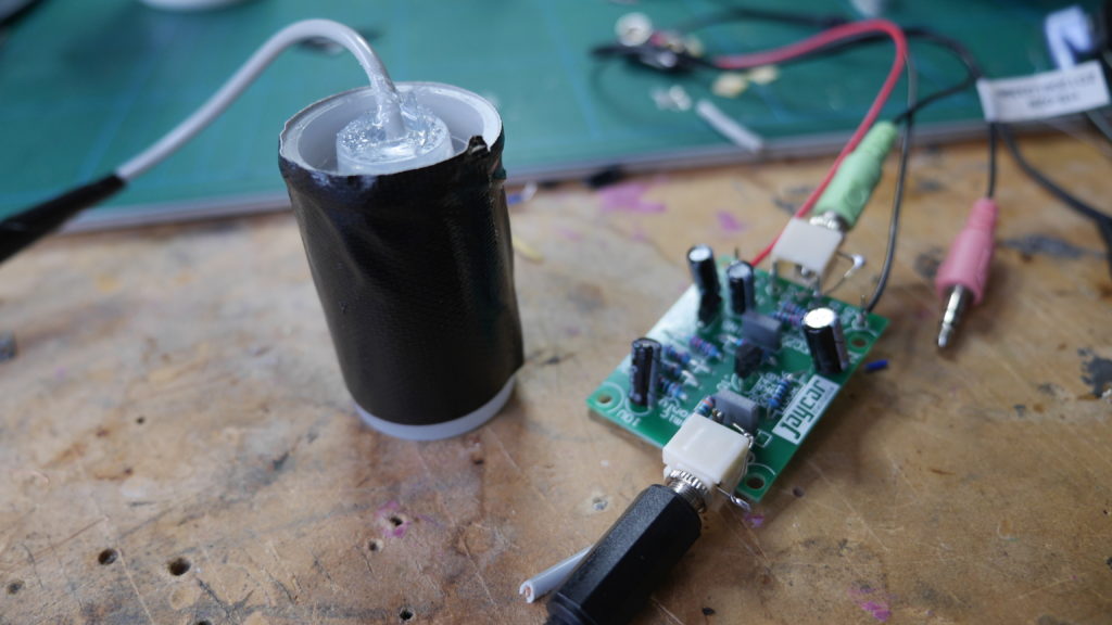
detail of the electret microphone in the film canister

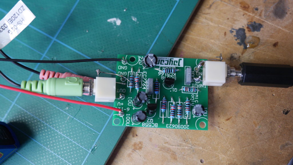
detail of the preamp (see similar component here)

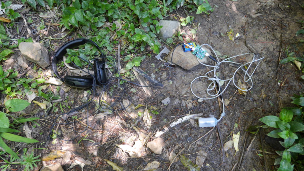
hydrophone without casing next to Papwai Stream

I built the hydrophone as described in Decker (2013) but used a 3.5mm mono headphone jack at the end of the 3 meter long cable. I also soldered 3.5mm sockets to the pre-amp for in- and outputs to keep the device as modular as possible. For testing the hyrdrophone I used a pair of headphones, but I will be looking into options for adding a speaker. Currently, the pre-amp turns on and off by connecting and deconnecting the battery, which is cumbersome, so adding a switch would be a good improvement overall to be added to a (preferably waterproof) enclosure.

Dawson, S. (2012, January 20). Building the “CETOS” directional hydrophone. Retrieved from http://whaledolphintrust.org.nz/wp-content/uploads/Building-Directional-HPs.pdf

Decker, F. C. (2013, June). Underwater sound detection using sea perch through construction and operation of hydrophone. Retrieved from https://seaperch.byu.edu/wp-content/uploads/2013/06/Final.pdf

digifishmusic. (2008, January). How to make a Hydrophone (stereo!). freesound. Retrieved from http://www.freesound.org/forum/production-techniques-music-gear-tips-and-tricks/2631/?page=1#post13253

The University of Waikato, New Zealand. (2011, May 10). Make and Use a Hydrophone. Retrieved October 17, 2016, from http://sciencelearn.org.nz/content/download/20964/411858/version/7/file/Make+and+use+a+hydrophone.doc