Lab EC-sensor tests

Before using more EC probes in the field and gathering data from different parts of the stream I tested them in a controlled environment in the lab.

Experiment 1: 

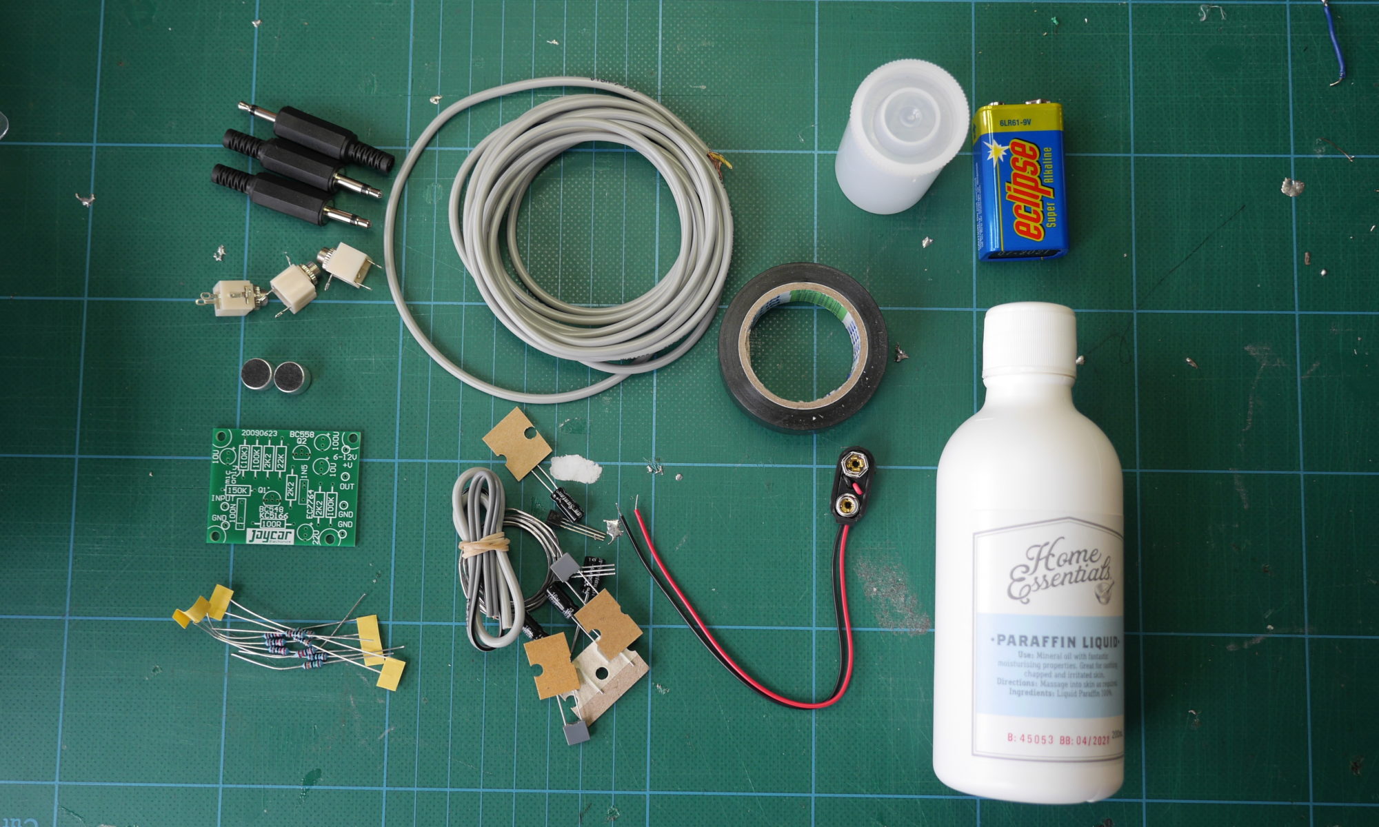
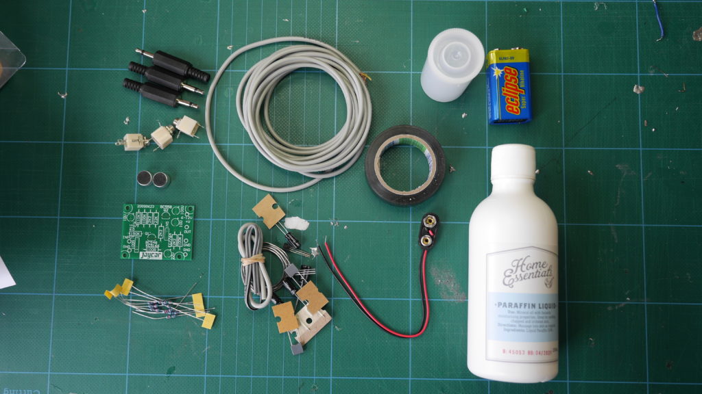
The two versions tested use the same materials, same length of chord and same 560 Ohm resistor. The first test involved a jar filled with tap water, immersing both sensors in the jar and monitoring the data via mosquitto_sub.

Jar filled with tap water for testing two DIY EC probes

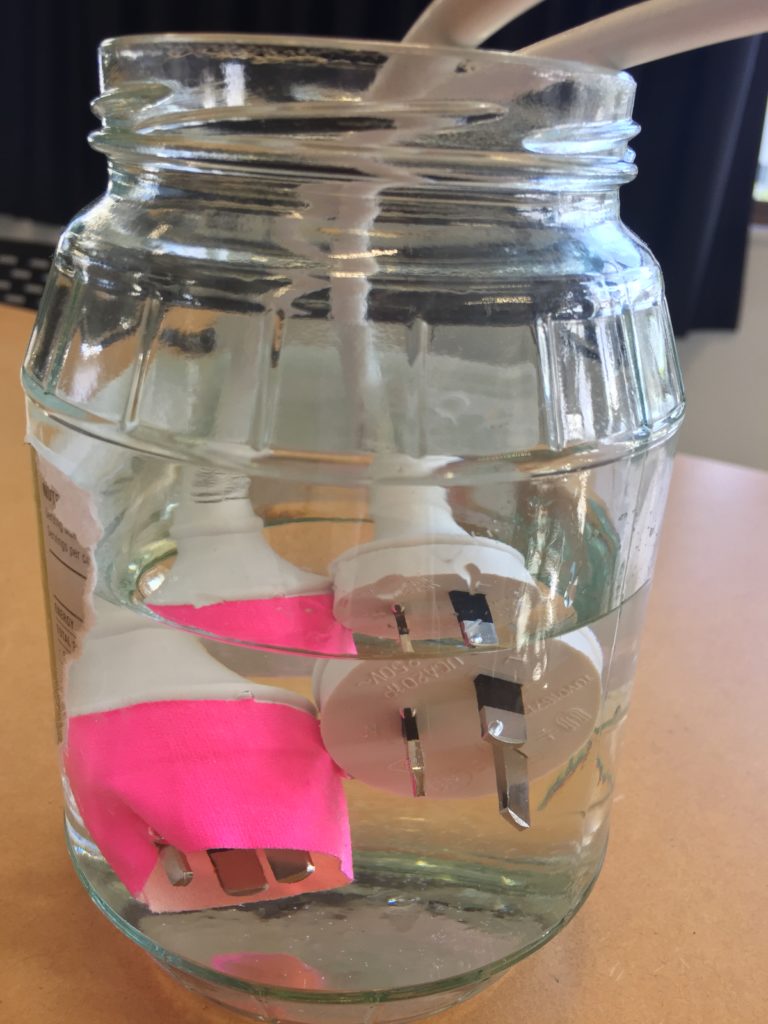
Note: The pink tape wrapped around one probe was an attempt to avoid the probe mistaken with a power plug on the lab table, which poses a severe hazard. The probes are stored away safely when unattended to ensure health and safety.  This version of the probe uses the Live (L) and neutral (N) prong of the plug. To improve the safety of the probe the live (L) prong should be removed and Neutral (N) and Ground (⏚) should be used for measuring the electric conductivity. 

The terminal output shows the EC probes publishing the measured values under the topics motorola/ec and moturoa/ecrua. While the test recording was done, the DHT11 sensor was also active in the lab, publishing air temperature (moturoa/atemp) and air humidity (moturoa/ahumid). Output showing values returned by two EC probes (moturoa/ec and moturoa/ecrua) and DHT11 sensor showing air temperature (moturoa/atemp) and air humidity (moturoa/ahumid)

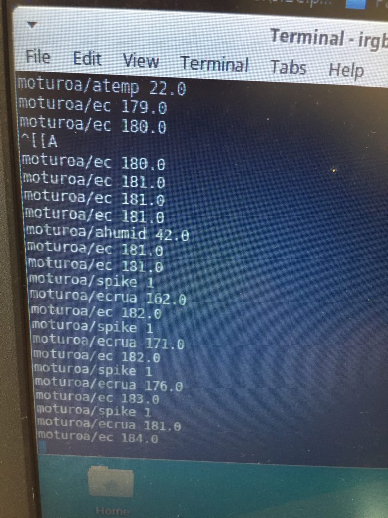
This first test showed a deviation of around 10 between both probes, behaving relatively consistent. The next test would require measurements in the stream to see whether the probes return coherent readings from flowing  water.

Experiment 2:

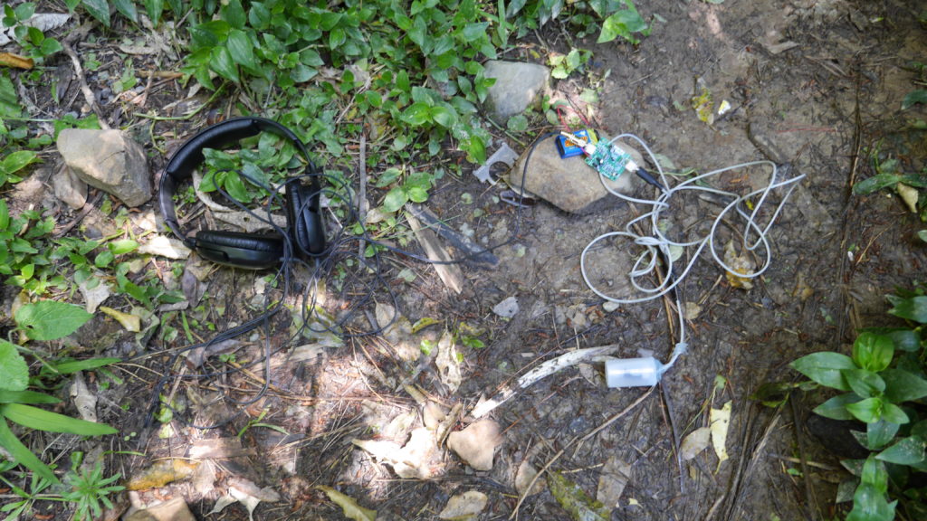
Due to bad weather and high winds it was too dangerous to conduct testing in the field. However, to get a better idea of the consistency between the two probes I went to an easily accessible part of the stream outside of the forested area and collected two samples of stream water. 

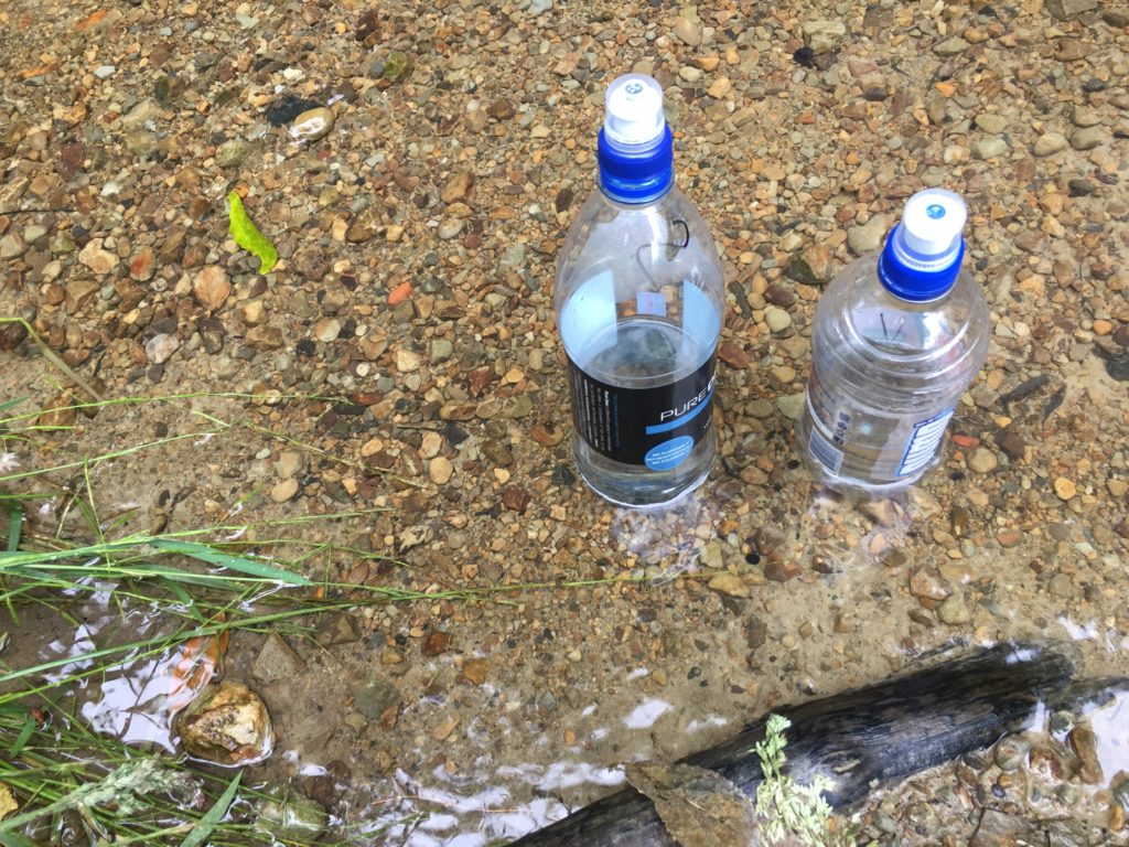
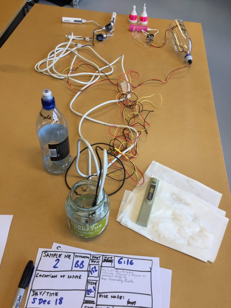
Back in the lab I pour the first sample into a clean jar that is big enough to contain all three sensors. I prepared a paper sheet for keeping experiment notes, starting with date/time, location of sample taken, last weather and readings from the TDS meter at the beginning and end of the test.

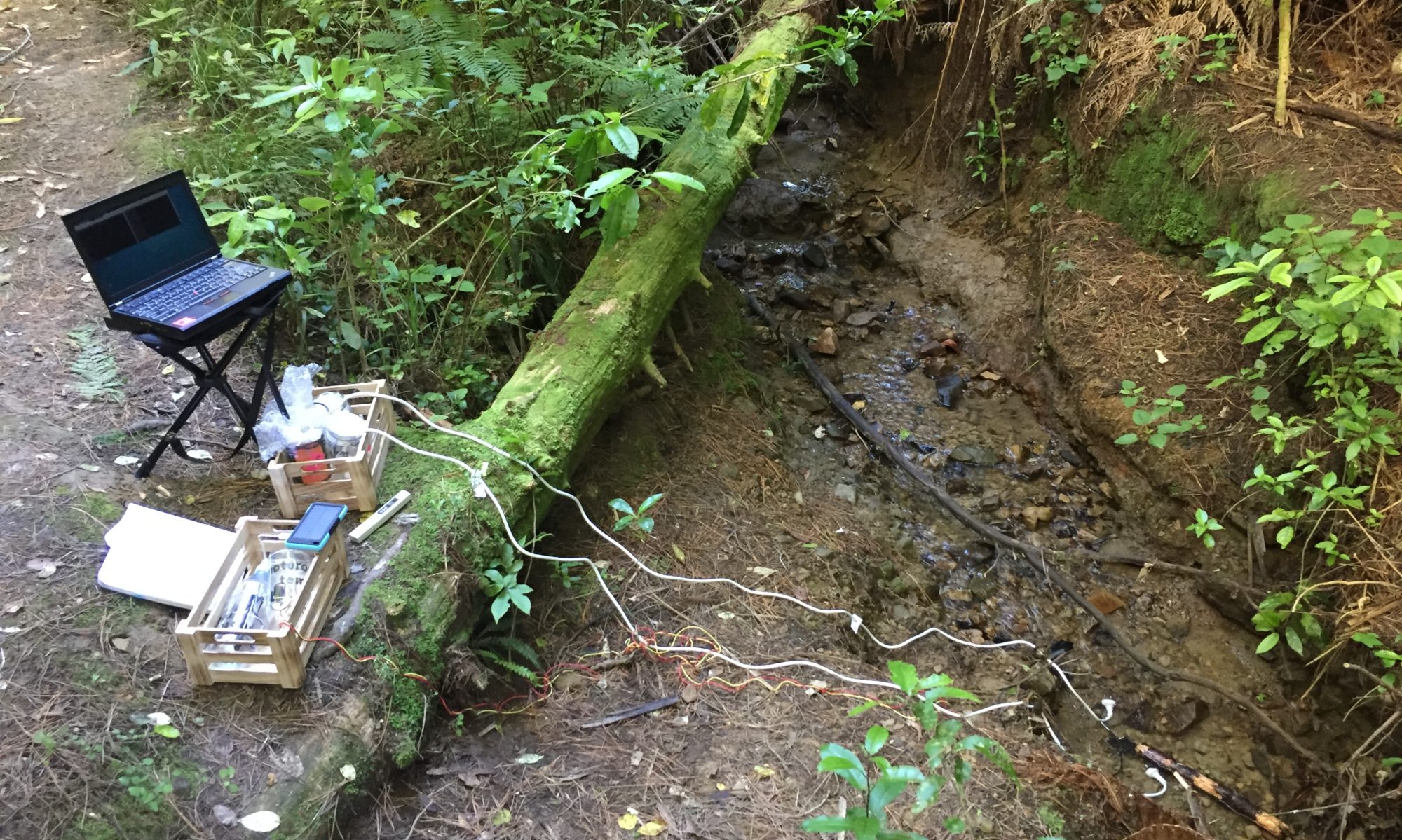
  1. I boot the Raspberry Pi (the Pi acts as Wi-Fi Access POint hosting the Moturoa_Transmissions network and acts as the MQTT-broker).
  2. Connect laptop to Moturoa_Transmissions and start log with timestamp
    mosquitto_sub -v -h 192.168.42.1 -p 1883 -t '#' | xargs -d$'\n' -L1 sh -c 'date "+%D %T $0"' > data.log
  3. Immerse probes into water sample and activate by connecting the Wemos D1 micro controllers to power supplies (USB batteries).

The raw data of both test results can be found on the development repository.

Building a low-cost hydrophone

For this research I want to explore what kind of DIY electronics can amplify the voice of the forgotten streams in Poneke/Wellington, New Zealand. As a first device I want to build a hydrophone that can be used during fieldwork to record underwater sounds.

Hydrophones used in scientific research, for acoustic monitoring, such as for tracking marine animals, are relatively expensive and even DIY solutions feature costly elements (see for example Dawson, 2012). In low-cost DIY solutions old audio components, such as headphones or radios are re-used (e.g. digifishmusic, 2008) and made waterproof with silicone or hot glue.

I decided to combine building a hydrophone based on two instructions. Both are based on using an electret microphone element as the primary component. In the instructions of Decker (2013) the element is enclosed in an empty film canister filled with mineral oil as a medium to optimize the hyrdophone. I chose this design for the first version following a suggestion on the Wellington Sonic Arts Facebook. The instructions by the University of Waikato (2011) feature a component list that is available in New Zealand.

components used for first hydrophone prototype

Building the first version of the hydrophone took less than a day and involved researching the best possible option to be done within one day, sketching a schematic alongside a shopping list of necessary parts, planning the quickest route around town to buy all necessary parts and then 2 hours of soldering and assembling plus some extra time for testing and troubleshooting and documenting along the way.

detail of the electret microphone in the film canister
detail of the preamp (see similar component here)
hydrophone without casing next to Papwai Stream

I built the hydrophone as described in Decker (2013) but used a 3.5mm mono headphone jack at the end of the 3 meter long cable. I also soldered 3.5mm sockets to the pre-amp for in- and outputs to keep the device as modular as possible. For testing the hyrdrophone I used a pair of headphones, but I will be looking into options for adding a speaker. Currently, the pre-amp turns on and off by connecting and deconnecting the battery, which is cumbersome, so adding a switch would be a good improvement overall to be added to a (preferably waterproof) enclosure.

Dawson, S. (2012, January 20). Building the “CETOS” directional hydrophone. Retrieved from http://whaledolphintrust.org.nz/wp-content/uploads/Building-Directional-HPs.pdf

Decker, F. C. (2013, June). Underwater sound detection using sea perch through construction and operation of hydrophone. Retrieved from https://seaperch.byu.edu/wp-content/uploads/2013/06/Final.pdf

digifishmusic. (2008, January). How to make a Hydrophone (stereo!). freesound. Retrieved from http://www.freesound.org/forum/production-techniques-music-gear-tips-and-tricks/2631/?page=1#post13253

The University of Waikato, New Zealand. (2011, May 10). Make and Use a Hydrophone. Retrieved October 17, 2016, from http://sciencelearn.org.nz/content/download/20964/411858/version/7/file/Make+and+use+a+hydrophone.doc